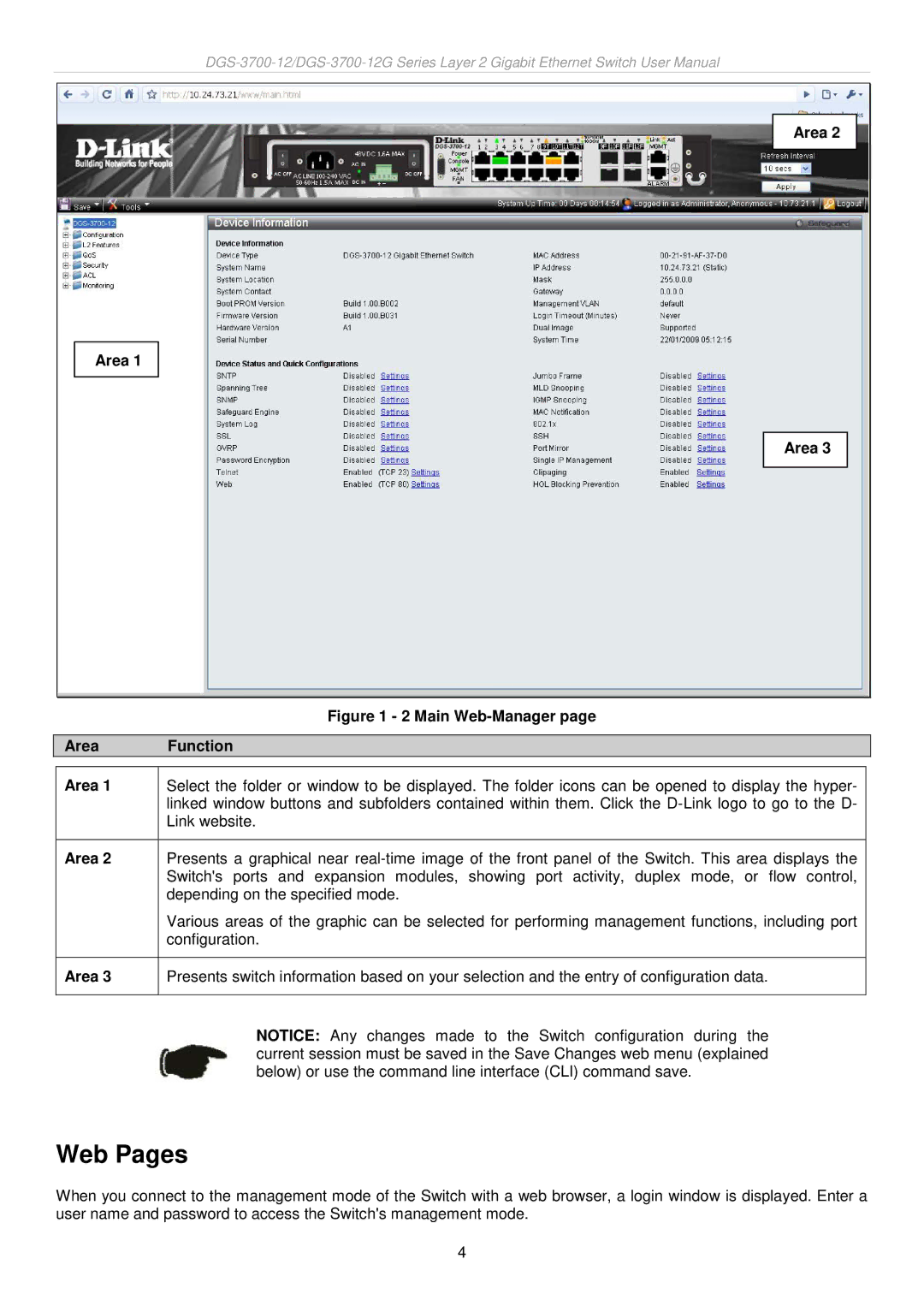
Area 2
Area 1
Area 3
|
| Figure 1 - 2 Main | |
|
|
|
|
| Area | Function | |
|
|
|
|
| Area 1 | Select the folder or window to be displayed. The folder icons can be opened to display the hyper- |
|
|
| linked window buttons and subfolders contained within them. Click the |
|
|
| Link website. |
|
|
|
|
|
| Area 2 | Presents a graphical near |
|
|
| Switch's ports and expansion modules, showing port activity, duplex mode, or flow control, |
|
|
| depending on the specified mode. |
|
|
| Various areas of the graphic can be selected for performing management functions, including port |
|
|
| configuration. |
|
|
|
|
|
| Area 3 | Presents switch information based on your selection and the entry of configuration data. |
|
|
|
|
|
|
| NOTICE: Any changes made to the Switch configuration during the | |
|
| current session must be saved in the Save Changes web menu (explained | |
|
| below) or use the command line interface (CLI) command save. | |
Web Pages
When you connect to the management mode of the Switch with a web browser, a login window is displayed. Enter a user name and password to access the Switch's management mode.
4