Sinumerik 810T
Users Guide Edition User Documentation
Basic Version Software Version Part 1 Operating
Basic Version Software Version Operating and Programming
January 1993 Edition
Edition Order No Remarks
Sinumerik Documentation
Printing history
Programming
Preliminary
Operating
· Part 1 Operating · Part 2 Programming
Technical comments
Part 1 Operating / Section
Terms/Abbreviations
Page
Contents
Preliminary remarks
Traverse to reference point Tools
Page
Page
Foto Nr E 3834 mittig 11 einmontieren
General Notes
Product
Siemens
· ·
Sinumerik 810T with external machine control panel
Sinumerik
Operation
Inputs from keyboard Softkey menu with 5 softkey functions
CRT display with softkeys
Screen edge
Softkeys
ETC key for extension of the same menu
ªOut of positionº display
ªAlarmº display
Display panel
Diagnosis
ªProgram runningº display
NC-MD
ªFeed holdº display
ªKey assignmentº
Address / numerical keys
Address for ºPosition informationº axis Z
Address for ºPosition informationº axis
Address for ºPosition informationº rotary axis
Address for ºPosition informationº auxiliary Axis Q
+/ ±
Delete word / block
Editing and input keys
Delete input / operator message
Modify word
Cursor movement in a part program
Control keys
Cursor left / right movement Cursor up/down movement
Paging up / down
Channel
Channel changeover
Function range of channels ·
Actual position in double height characters
Acknowledge alarm
810T Bild 1 von Druckerei einmontieren
Search for address / block no. / word / calling up data
Diagnostics and start up
Or when you want to display on the screen
Foto-Nr T Einmontieren
Description of the keys Reset
Integrated machine control panel
Spindle stop / Spindle start
Single block
Program stop / Program start NC stop / NC start
Feed hold/ Feed start
Example for the use of ºSpindle stopº
± Z ± Q ±
Continuous mode Jog mode
+X +Q
Direction keys / Jogging
± Q
Continuous mode
± Z
Function of the direction keys
Operate Key
Extension of the operating mode menu is shown
Key for the selection of operating modes
Operate Key a second time
Spindle speed override decrease / increase
2nd continuation of the operating mode menu is shown
Operate the ETC
Operate Key quickly
Feed or rapid traverse override decrease / increase
Socket connector for universal interface
For D-type sub-miniature connectors
To or from peripheral devices
09.91
Foto Nr E 3844 11 mittig einmontieren
Foto Nr E 3840 mittig einmontieren
Explanation of the operating Emergency stop switch
External machine control panel
Manual Data Input MDI Automatic
Actual Value Preset
Setting
Automatic
Single block switch
Spindle speed override switch
01.93
By operating this key, you switch the NC control on
Feed / rapid override switch
Switch for switching on the NC control
Key-operated switch for input inhibit / operation inhibit
Examples of the use of ºSpindle stopº
Feed stop/Feed start
Examples of the use of ºFeed stopº
+X +Q ± Z ± Q ±
Direction keys/traversing axes in ºJOGº mode
± in continuous mode ± in jog mode Continuous mode
ºrapid traverseº rate is defined in machine data
01.93
09.91
810T Bild 2 von Druckerei einmontieren
Switching on / off
Switching off the control
Darkening the screen
Following different operating modes are available
Operating modes General
Operating modes overview
· Automatic operation CRT display Automatic
810T Bild 6 von Druckerei einmontieren
810T
Bild 5 von Druckerei
· Manual data input / Automatic CRT display MDI Automatic
810T Bild 9 von Druckerei einmontieren
810T Bild 7 von Druckerei einmontieren
810T Bild 8 von Druckerei einmontieren
Sinumerik 810T, GA3 BN
By operating this key on the machine control panel
Operate the ETC key Under the CRT display once
Menu
Softkey
Manual Data Input MDI-AUTOMATIC
Feed
4 ºResetº with change of operating mode
Examples
Branching to operating functions within an operating mode
Etc
Example
Menu display from the NC program or from the PLC
810T Bild 3 von Druckerei einmontieren
810T Bild 13 von Druckerei einmontieren
Selected Mode
· ºGUIDINGº operator prompting function
Operating mode menu trees
· ºAUTOMATICº mode · ºJOGº mode
1 ºAUTOMATICº mode
Option
Block Search Program DIAG- Control Nosis Over Store OPS
Sinumerik 810T, GA3 BN
2 ºJOGº mode
JOG Tool Setting Data Part Diag Offset IN-OUT Program Nosis
Over Autom Store
System User Data Bits General Axial Spindle Mach Channel
4 ºMDI AUTOMATICº mode
5 ºREFPOINTº mode
Sinumerik 810T, GA3 BN
Sinumerik 810T, GA3 BN
INC Feed 1
6 ºINC 1 ... INC 10 000º mode
Tool Offset Setting Data IN-OUT Part Diag Program Nosis
Hand Wheel Over Store
7 ºPRESETº mode
Preset Store Clear PRE-OFF
Tool Offset Setting Data Data IN-OUT Part Program Diag
Sinumerik 810T, GA3 BN
ºREPOSº mode
Repos Tool Setting Diag Over Offset Data Nosis
See Next
9 ªGUIDINGº operator prompting function
Block G Number Funct Line Circle Thread
ªGUIDINGº operator prompting function
Contour WORK- Cycle Feed Spindle Tool
BA B
Special ADD Program Block Funct END
Sinumerik 810T, GA3 BN
Glossary of softkey functions
You enter the simulation area and the workpiece dimensions
You clear the Preset offset
Circle
You start data input via the universal interface
When ºYESº, the differential resolver function is activated
Data IN-OUT
DRY RUN YES-NO
Output of the end of block character end of text
NC machine data are displayed
All current NC alarms are displayed see Section
Location number and tool number of worn tools is displayed
All current PLC messages are displayed see Section
All current PLC alarms are displayed see Section
º Part PROGRAMº softkey leads to
DD PARALL. =
Input of setting data for scale modification
Simulation is interrupted and returned to the reset state
Input of setting data for coordinate system rotation
Key leads to the following functions
Special Block
You activate the selected softkey function
ºPLAYBACKº mode you store the position traversed to
Store the Preset values entered axis-specifically
You stop the activated softkey function
Select the G functions for thread cutting with this softkey
You input the tool number T... and the tool offset number D
ZO Autom
Operating Sequences
Preliminary remarks
Traverse to reference point
Preparation Switching on
When you switch the control and machine on
Sequence of operation
Operating Sequences Traverse to reference point
Tool Offset
Tools
Tool offset Input of tool offset
P1 = P1=7 P1=4
P1 =
P1=
Geometry values of the available tool types
L2 Geometry Diameter/radius
L1 Wear L2 Wear Diameter/radius
L2 Basic
Bild 810T/16 einmontieren
Operating Sequences 3.1.4 Tool offset 09.91
Delete
Using the numerical keys you enter a new value
Deleting/modifying an individual offset value
Modification
11.90
Deleting all offset values in an offset number D
Joginc Autom Tool
Automatic tool offset
Bild 810T/17 einmontieren
Store Axis
Bild 810T/15 einmontieren
Integrated tool
Input of tool data
Tool Data
Down Geom Data
Bild 810T/58 einmontieren
Enter
Display of tool data
Tool Offset Geom Data
Next
Bild 810T/59 einmontieren
List Tools
Display Data
Zero offset
ZFP XMR ZMW XFP ZMR
810T Bild 18 von Druckerei einmontieren
Any operating mode, operate the ºSETTING DATAº Softkey
Settable zero offsets
Zero Offset
Input key
X axis into the input line, using the numerical
Now enter the value for the coarse offset ºG54º for
Programmable zero offsets
Programmable zero offset external zero offset
Bild 810T/19 einmontieren
Precondition
External zero offset
Press the ºSETTING DATAº softkey Any mode
Bild 810T/20 einmontieren
EXT
INC
Automatic calculation of the zero offset
Bild 810T/21 einmontieren
Setting data ºR PARAMETERSº
Sinumerik 810T, GA3 BN
Local parameters Scratchpad flags
Overview of the R parameters in each channel Channel
Transfer parameters
Global parameters
Channel-specific R parameters 0-699/ Central R parameters
Sinumerik 3/8
Operating Sequences 09.91
Para Meter
Sequence of operation for ºR PARAMETERº setting data
Bild 810T/22 einmontieren
Unit
ºSPINDLEº setting data
Standard Maximum Input
Oriented spindle stop
Sequence of operation for ºSPINDLEºsetting data
Bild 810T/23 einmontieren
Axial
ºAXIALº setting data
Sequence of operation for ºAXIALº setting data
DRF Assignm
810T Bild 24von Druckerei einmontieren
Bild 810T/25 einmontieren
Rotat Angle
ºANGLE of ROTATIONº setting data
Sequence of operation for ºANGLE of ROTATIONº setting data
Scale Modif
ºSCALE MODIFICATIONº setting data
Sequence of operation for ºSCALE MODIFICATIONº setting data
Part PROG. Edit
Flexible plane selection
Bild 810T/57 einmontieren
Plane
Store Plane
G16 Plane Store Plane
Function of the modes with ªaxis synchronizationº
ªPRESETº and ªREFPOINTº modes
Axis
Axes of the two tool systems can only be moved separately
Operating Sequences 09.91 Axis synchronization
Transmit coordinate transformation
Behaviour of the transformation in the modes
± ªJOGº state
± ªAUTOMATIC passiveº state
± ªAUTOMATIC activeº state
± ªJOGº Automatic interrupted state
ªREPOSº mode
ªAUTOMATICº and ªMDI AUTOMATICº mode
ªREFPOINTº mode
Transmit function in the various modes
± Follow-up mode
ªPRESETº mode
ªTEACH INº/ªPLAYBACKº mode
Special cases ± ªDRF/handwheelº active
Display of the Transmit function
Sequence
Program input
Program input with the keyboard
Part Program
Operate the ºEDITº softkey
Bild 810T/11 einmontieren
Edit
Select Program
Example Entering an individual block
Program input with operator guiding
Guiding
Operating Sequences 11.90 Program
Enter the desired program no. º%12º
Guiding Block Number
G00
Func Tions
G90
Block END
Contour
Select the ºCONTOURº softkey
Call desired program using ºSELECT PROGRAMº
Store them using the input key
Line Circle
Bild 810T/28 einmontieren Bild 810T/27 einmontieren
Bild 810T/29 einmontieren
Delete Param Store
Operating Sequences
You wish to edit
Part Program Edit
Or ºL...º number of the program
Program Select
Insert word Modify word Delete word Insert block
X.....LF
Delete block
Part Corr Program Block
Preset / JOG / Automatic / INC 1 .... INC 10 000 / Refpoint
Correction display ºCORRECTION BLOCKº
Value
Bild 810T/30einmontieren
Preset / JOG / Automatic
When the display is full
Partdirec Program Tory
Part Direc SUB Program Tory Rout
Preset / JOG / Automatic
Protection of subroutines cycle lock
Lock
Cycle lock release ºENABLEº
Enable
Part Program Program Handling
Copying a program ºCOPYº
Bild 810T/31 einmontieren
Copy
Part Prog Program Handl Move
Preset / JOG / Automatic INC1... ICN10 000/ Refpoint
Moving a program ºMOVEº
Renaming a program ºRENAMEº
Part Prog Program Handl Rename
Sinumerik 810T, GA3 BN
INC 1...INC 10 000 / Refpoint
Deleting a program ºDELETEº
Part Prog Program Handl Delete
Deleting an individual program
Reorg
Reorganizing the program memory ºREORGº
Part Prog Program Handl
Direc Tory
13.9 ºSelecting a programº
Operator guidance macros OGM and back translation
Example of a data block
Store Input Display
Example of the result of a part program
Back translation
Change data as required
Find Block
Function Find Block using block number Precondition
OGM
Delete Block
Part program 1234
Any of the operating modes
14 ºSIMULATIONº
Simulation ºAREA of the WORKPIECEº
Area Piece
810T Bild 32 von Druckerei einmontieren
Select SIMULA- Program Tion
Influencing simulation
Reset
If you press ªRESETº softkey, simulation is aborted
Simula Tion Start
Program Control
Bild 810T/33 einmontieren
ªPROGRAM CONTROLº
Simula Tion
Block Search
Bild 810T/34 einmontieren
ªBLOCK SEARCHº
Start
Bild 810T/35 einmontieren
Data input/data output
Setting Bits
Setting data bits
Explanation of setting data structure
5011
Bild 810T/36 einmontieren
INC 1 .... INC 10 000 / Refpoint
Data input
810T Bild 37 von Druckerei einmontieren
DATA-IN Start
Data type Meaning
Data Data IN-OUT Output
Data output
Bild 810T/38 einmontieren
Any of the operation modes
Mainprg Subrout Start
810T Bild 39 von Druckerei einmontieren
This input form appears
MAINPRG. Subrout Start Start
Operate the ºR parameterº softkey
ETX Start
Refpoint
Part program block
Data IN-OUT BTR Start
· Protected transmission
Circular buffer
· Unprotected transmission
NC in two languages
Machining Starting a part program
Auto Matic
Machine control panel to this symbol
An active program is being processed in ºAUTOMATICº mode
Set the operating mode selector switch on the external
Machine control panel, and then the ºAUTOMATICº
810T Bild 13 von Druckerei einmontieren
Operate the ºCURRENT BLOCKº softkey
810T Bild 42 von Druckerei einmontieren
Current Block
Explantion of the ºCURRENT BLOCKº display
Influencing ºAUTOMATICº operation
Skip Block YES-NO
Influencing the program
Bild 810T/43 einmontieren
Display Skip block
Overr YES-NO
DRY YES-NO
OPT Stop YES-NO
DEC-SBL YES-NO
Block type Single block
Decoding single
09.91
You extend the softkey menu called under ºPROGRAM CONTROLº
Subsequently operate the ºDRF-HANDWHEEL-ENABLEº softkey
810T Bild 44 von Druckerei einmontieren
DRF YES-NO
Over Store
3.2 ºOVERSTOREº
810T Bild 46 von Druckerei einmontieren
Operating Sequences Influencing ºAUTOMATICº operation
3.3 ºBLOCK SEARCHº
Auto Matic Block Search
Operate the ºSTARTº softkey
Foto Nr T/47 einmontieren
Number º ... º for the search destination,
102
103
+X +Q ± Z +Z ± Q
Repos
Interrupting
By NC Stop
810T Bild 49 von Druckerei einmontieren
You are in the Automatic mode
Program sequencing
Automatic
105
Creating a new file
Remote operation functions
NEW
File
Deleting a file
Extend
File Clear File
Reading in a file
Creating the program sequence list
810T Bild 48 von Druckerei einmontieren
Directory of diskette
Input OPS
109
Down Delete List
Program sequencing =OPS
You operate the ªRUN OPSº softkey
810T Bild 50 von Druckerei einmontieren
RUN
Interrupt program sequencing
Start OPS
OPS Start
Edit Interruption
Continuation
Stop Edit Start OPS
End
Types of data
113
MDI
4 ºManual data input automaticº MDI Automatic mode
810T Bild 5 von Druckerei einmontieren
115
115
5 ºTEACH INº
Part Teach Program PL. Back
INC
6 ºPLAYBACKº
JOG
+X +Q ± Z +Z ± Q ±
810T Bild 54 von Druckerei einmontieren
Continuing Teach in / Playback after Reset
Set the mode selector switch to the symbol for ºAUTOMATICº
Part Teach Program PL.BACK
Teach PL.BACK
7 ºJOGº mode
± Z ± Q
8 ºIncrementalº mode ºINC Feed 1 ... INC Feed 10 000º
10, 100, 1000, 10000 increments
· ºModalº · º Jog operationº
123
9 ºHANDWHEELº
Handwheel
Enable of the handwheels connected
810T Bild 53 von Druckerei einmontieren
10 ªDRFº Siemens AG 1990 All Rights Reserved 6ZB5 410-0EP02
Auto Matic Program Control
10 ºDRFº
810T Bild52 von Druckerei einmontieren
Select the ºDRFº softkey function
DRF YES no
DRF
DRF offset with connected handwheels
11 ºActual value settingº mode ºPRESETº
129
Clear PRE-OFF
12 ºRepositioningº mode ºREPOSº
Red ºFeed holdº LED display is extinguished 132
Prerequisite
This display appears on the CRT
133
Scratching
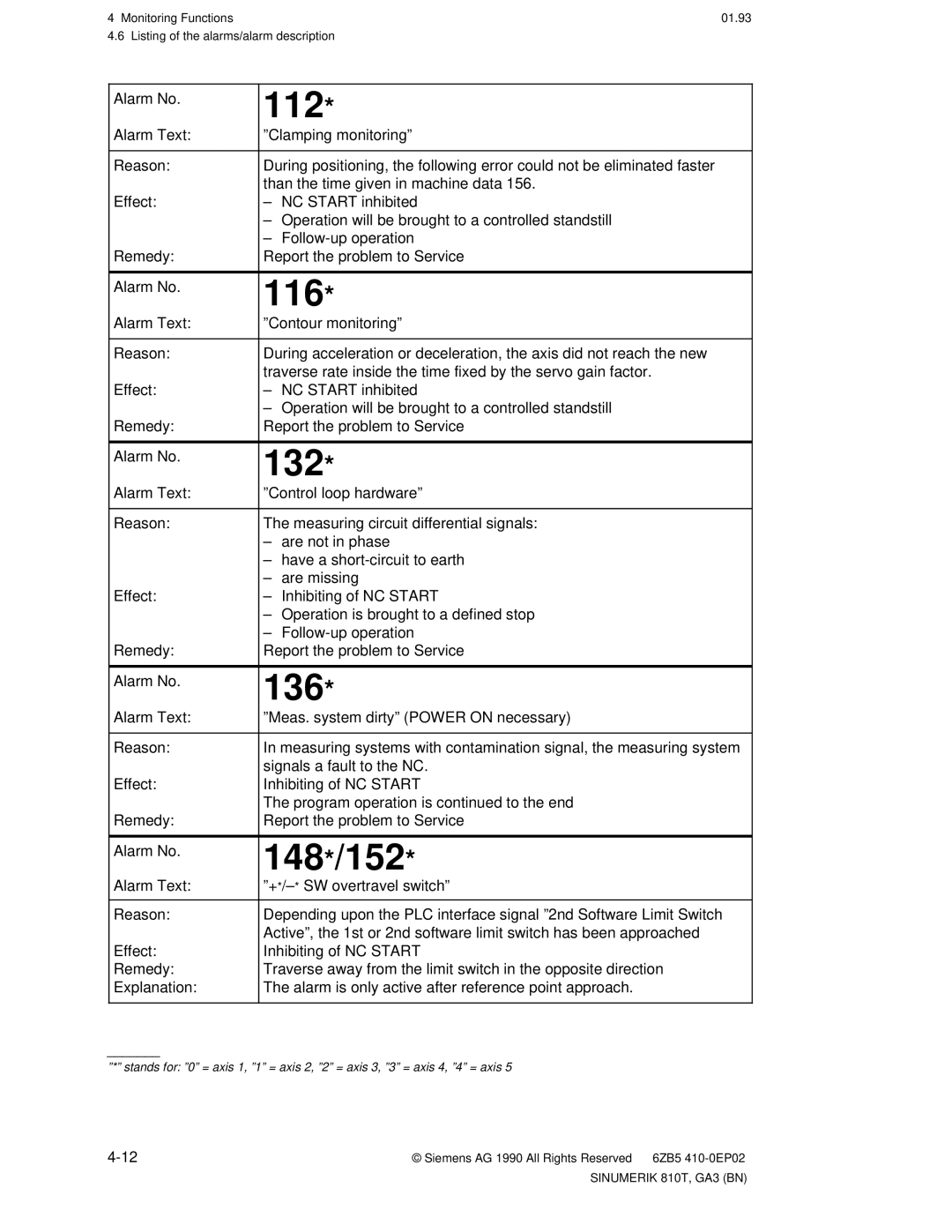
Monitoring Functions
Diagnostics display on the CRT
Alarm Line
Further Identifiers
116* ORD12 Contour Monitoring
Display representation
ORD 2 Spindle speed too high
· Example of display representation type a
PLC S value in BCD not allowed
2155 * N 45 Option M19 error
Valid for alarm numbers 2000 ... partly and 3000 ... partly
· Example of display representation type C
Alarm number Alarm group Alarm cleared by
Alarm numbers and groups/delete alarms
NC alarms
NC Alarm
DIAGNOSTICS/selection of further alarms
Listing of the alarms/alarm description
PLC Alarm
Sinumerik 810T, GA3 BN
Sinumerik 810T, GA3 BN
11.91
TEA5
TEA1
TEA2
TEA6
11.90
Sinumerik 810T, GA3 BN
104
108
132
112
116
136
168
156
160
172
2000
184
196
2030
2034
2031
2032
2035
2041
2039
2040
2042
2048
2046
2047
2056
2061
2059
2060
2062
2066
2064
2065
2067
Sinumerik 810T, GA3 BN
2074
2072
2073
2075
2082
2078
2081
2087
2155
2153
2154
2160
2190
2184
2189
2191
226
2194
225
227
3001
228
3000
3002
3006
3004
3005
3009
3007
3008
3010
3016
3012
3013
3017
3024
3020
3021
3025
3030
3028
3029
3032
3046
3042
3043
3048
3083
3081
3082
3084
4101
3201
4100
4102
Handling
Maintenance
Operating data
Replacing the battery in the battery receptacle
Schematic of the back of the Sinumerik 810T
CRT display
Cleaning
Setting data for description of the interfaces
Data Interfaces
5010
Setting data function
SD no
5011
RTS Line PLC Prog
SD no
Sinumerik
RTS Line PD / PF
Device connection data
Sinumerik WS
Siemens Programmer PG 675/685
Siemens Programmer PG 685/675/670/730/750
Operating conditions
Siemens printer PT88
Setting of the operating mode switches
Siemens page printer PT80
OFF OFF OFF
· possible Order Options which influence the operation
Interfacing to the Machine
Ordering data Options
B03 + B75 +
Precludes PLC memory expansion
EPROM-UMS
Order Code Option
Comments
09.91 Interfacing to the Machine
To call up the CRT display, proceed as follows
Sinumerik 810T machine data General machine data
Sequence of operation Calling general machine data
Diag Nosis
NC MD
Sinumerik 810T, GA3 BN
Cycle MD Cycle SD
Definition of area limits with general NC MC 14 to
As displayed on the screen
5013
Machine data bits
To call the CRT display, proceed as follows
Sequence of operation calling machine data bits
Machine Bits
NC MD Channel Data
Definition of the initial setting of the G groups
Press the ªDIAGNOSISº softkey
NC MD for the initial settings of the G groups Channel Data
Active in individual blocks Basic setting on M or T version
Bit No 560
Setting data General SD bits
Axis-specific bits
Spindle-specific setting data
Significance of ºxº 0=Spindle 1 1=Spindle
Appendix
List of abbreviations Mnemonics Meaning
Mnemonics Meaning
RAM
List of terms used Term
Section
Current Block Current Values
Diagnostics
Copy CORR. Block
Cycles Data in OUT
EXT Start
Emergency Stop Enable
Erase
Feed
NC MD
Move NC Alarm
Machining Cycle MACH. Data Main Program Mainprg Start
OPS
Part Program Plane Playback
PLC Alarm PLC/MD PLC Message PLC Status
Reset
Program Control
Term Section
Tool Data
Subroutine Start
Teach Thread Tool
Tool Offset
Sinumerik 810T operator interface Layout
Sinumerik 810T with integrated machine control panel
Sinumerik 810T with external machine control