Typical Connection Diagram
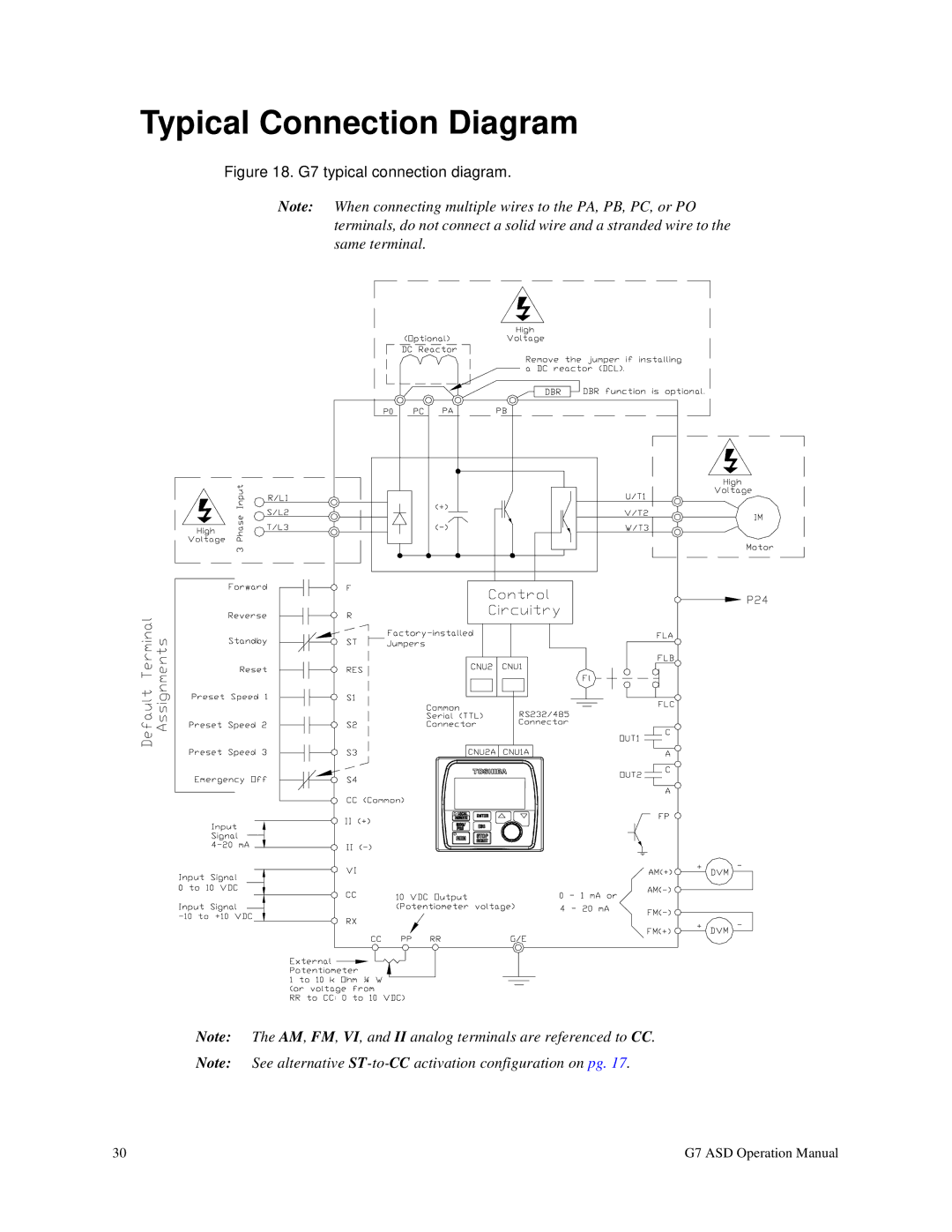
Figure 18. G7 typical connection diagram.
Note: When connecting multiple wires to the PA, PB, PC, or PO terminals, do not connect a solid wire and a stranded wire to the same terminal.
Note: The AM, FM, VI, and II analog terminals are referenced to CC.
Note: See alternative
30 | G7 ASD Operation Manual |