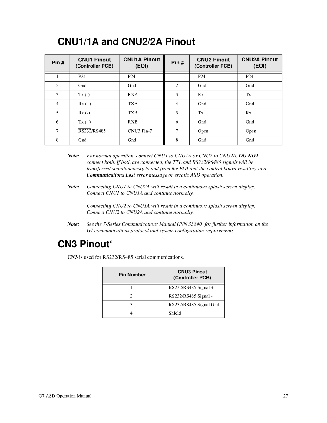
CNU1/1A and CNU2/2A Pinout
Pin # | CNU1 Pinout | CNU1A Pinout |
| Pin # | CNU2 Pinout | CNU2A Pinout | ||
(Controller PCB) | (EOI) |
| (Controller PCB) | (EOI) | ||||
|
|
| ||||||
|
|
|
|
|
|
|
|
|
|
|
|
|
|
|
|
| |
1 |
| P24 | P24 |
| 1 | P24 | P24 | |
|
|
|
|
|
|
|
| |
2 |
| Gnd | Gnd |
| 2 | Gnd | Gnd | |
|
|
|
|
|
|
|
| |
3 |
| Tx | RXA |
| 3 | Rx | Tx | |
|
|
|
|
|
|
|
| |
4 |
| Rx (+) | TXA |
| 4 | Gnd | Gnd | |
|
|
|
|
|
|
|
| |
5 |
| Rx | TXB |
| 5 | Tx | Rx | |
|
|
|
|
|
|
|
| |
6 |
| Tx (+) | RXB |
| 6 | Gnd | Gnd | |
|
|
|
|
|
|
|
| |
7 |
|
|
| CNU3 |
| 7 | Open | Open |
| RS232/RS485 | |||||||
|
|
|
|
|
|
|
| |
8 |
| Gnd | Gnd |
| 8 | Gnd | Gnd | |
|
|
|
|
|
|
|
|
|
Note: For normal operation, connect CNU1 to CNU1A or CNU2 to CNU2A. DO NOT connect both. If both are connected, the TTL and RS232/RS485 signals will be transferred simultaneously to and from the EOI and the control board resulting in a Communications Lost error message or erratic ASD operation.
Note: Connecting CNU1 to CNU2A will result in a continuous splash screen display. Connect CNU1 to CNU1A and continue normally.
Connecting CNU2 to CNU1A will result in a continuous splash screen display.
Connect CNU2 to CNU2A and continue normally.
Note: See the
CN3 Pinout‘
CN3 is used for RS232/RS485 serial communications.
Pin Number | CNU3 Pinout | |
(Controller PCB) | ||
| ||
|
| |
|
| |
1 | RS232/RS485 Signal + | |
|
| |
2 | RS232/RS485 Signal - | |
|
| |
3 | RS232/RS485 Signal Gnd | |
|
| |
4 | Shield | |
|
|
G7 ASD Operation Manual | 27 |