Installation and Connections
The G7 True Torque Control2 Adjustable Speed Drive may be set up initially by performing a few simple configuration settings. To operate properly, the ASD must be securely mounted and connected to a power source
Note: The optional
the ASD. See the section titled G7 Optional Devices on pg. 200 for further information on the available options.
The output terminals of the ASD (T1/U, T2/V, and T3/W) must be connected to the motor that is to be controlled (see Figure 18 on pg. 30).
As a minimum, the installation of the ASD shall conform to Article 110 of the 2002 NEC, the Occupational Safety and Health Administration requirements, and to any other local and regional industry codes and standards.
Upon initial system powerup, the Startup Wizard starts automatically. The Startup Wizard assists the user with the initial configuration of the G7 True Torque Control2 Adjustable Speed Drive. See the section titled Initial Setup on pg. 38 for additional information on the Startup Wizard.
Installation Notes
When a
If an output contactor is used for bypass operation, it must be interlocked such that commercial power is never applied to the output terminals of the ASD (T1/U, T2/V, or T3/W).
If a secondary magnetic contactor (MC) is used between the output of the ASD and the motor, it should be interlocked such that the ST – CC connection is disconnected before the output contactor is opened.
Do Not open and then close a secondary magnetic contactor between the ASD and the motor unless the ASD is off and the motor is not rotating.
Note:
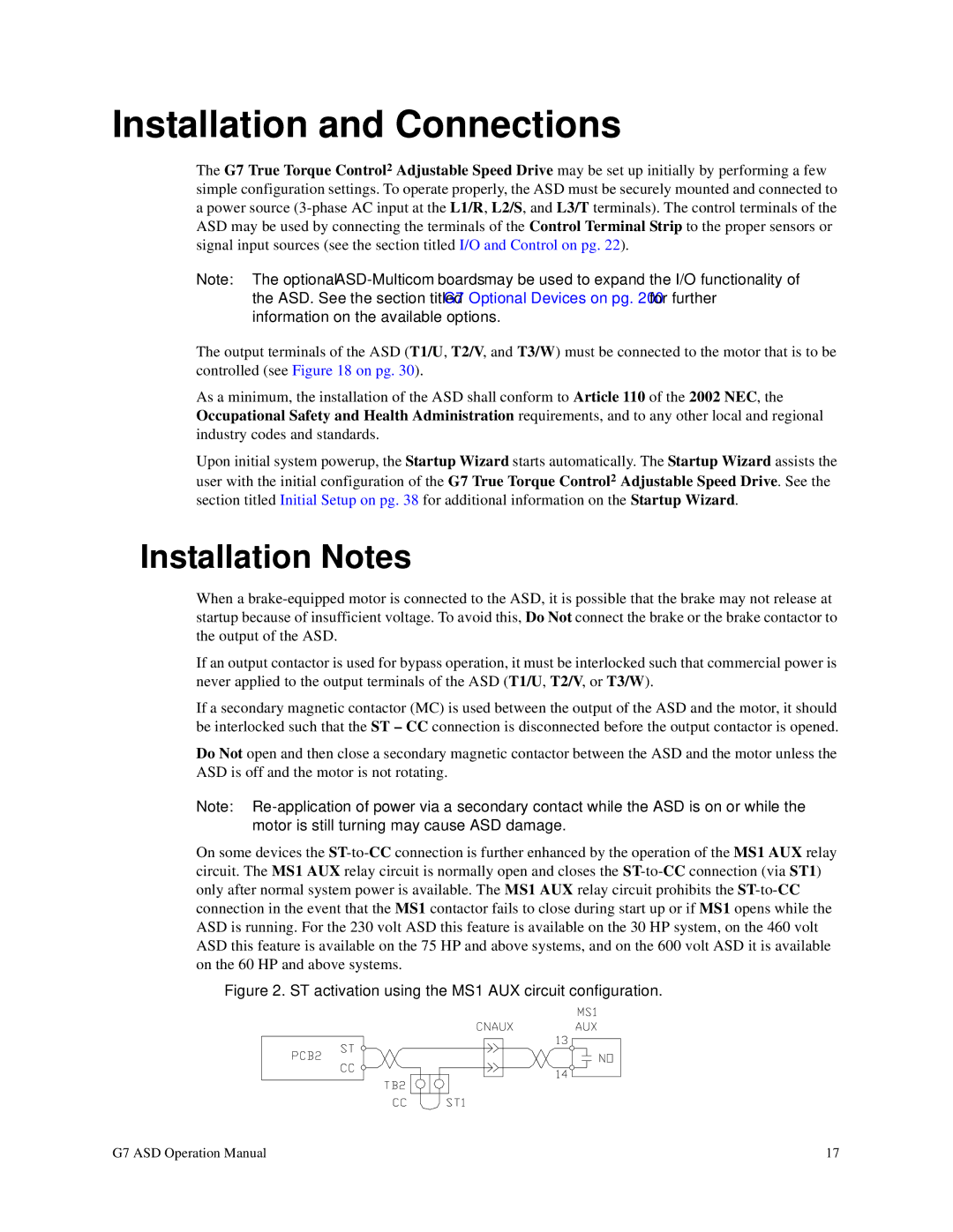
On some devices the
Figure 2. ST activation using the MS1 AUX circuit configuration.
G7 ASD Operation Manual | 17 |