F004 | F006 |
Frequency Mode #1
Program ⇒ Fundamental Parameters ⇒ Standard Mode Selection ⇒
Frequency Mode #1
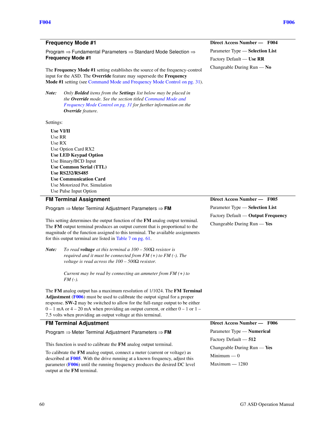
The Frequency Mode #1 setting establishes the source of the
Direct Access Number — F004
Parameter Type — Selection List
Factory Default — Use RR
Changeable During Run — No
Note: | Only Bolded items from the Settings list below may be placed in |
|
| |
| the Override mode. See the section titled Command Mode and |
|
| |
| Frequency Mode Control on pg. 31 for further information on the |
|
| |
| Override feature. |
|
| |
Settings: |
|
|
| |
Use VI/II |
|
| ||
Use RR |
|
| ||
Use RX |
|
| ||
Use Option Card RX2 |
|
| ||
Use LED Keypad Option |
|
| ||
Use Binary/BCD Input |
|
| ||
Use Common Serial (TTL) |
|
| ||
Use RS232/RS485 |
|
| ||
Use Communication Card |
|
| ||
Use Motorized Pot. Simulation |
|
| ||
Use Pulse Input Option |
|
| ||
|
|
| ||
FM Terminal Assignment | Direct Access Number — | F005 | ||
Program ⇒ Meter Terminal Adjustment Parameters ⇒ FM | Parameter Type — Selection List | |||
This setting determines the output function of the FM analog output terminal. | Factory Default — Output Frequency | |||
Changeable During Run — Yes | ||||
The FM output terminal produces an output current that is proportional to the | ||||
|
| |||
magnitude of the function assigned to this terminal. The available assignments |
|
| ||
for this output terminal are listed in Table 7 on pg. 61. |
|
| ||
Note: | To read voltage at this terminal a 100 – 500Ω resistor is |
|
| |
| required and it must be connected from FM (+) to FM |
|
| |
| voltage is read across the 100 – 500Ω resistor. |
|
| |
| Current may be read by connecting an ammeter from FM (+) to |
|
| |
| FM |
|
| |
The FM analog output has a maximum resolution of 1/1024. The FM Terminal |
|
| ||
Adjustment (F006) must be used to calibrate the output signal for a proper |
|
| ||
response. |
|
| ||
0 – 1 mA or 4 – 20 mA when providing an output current, or either 0 – 1 or 1 – |
|
| ||
7.5 volts when providing an output voltage at this terminal. |
|
| ||
|
|
| ||
FM Terminal Adjustment | Direct Access Number — | F006 | ||
Program ⇒ Meter Terminal Adjustment Parameters ⇒ FM | Parameter Type — Numerical | |||
This function is used to calibrate the FM analog output terminal. | Factory Default — 512 |
| ||
Changeable During Run — Yes | ||||
To calibrate the FM analog output, connect a meter (current or voltage) as | ||||
Minimum — 0 |
| |||
described at F005. With the drive running at a known frequency, adjust this |
| |||
|
| |||
parameter (F006) until the running frequency produces the desired DC level | Maximum — 1280 |
| ||
output at the FM terminal. |
|
| ||
60 | G7 ASD Operation Manual |
