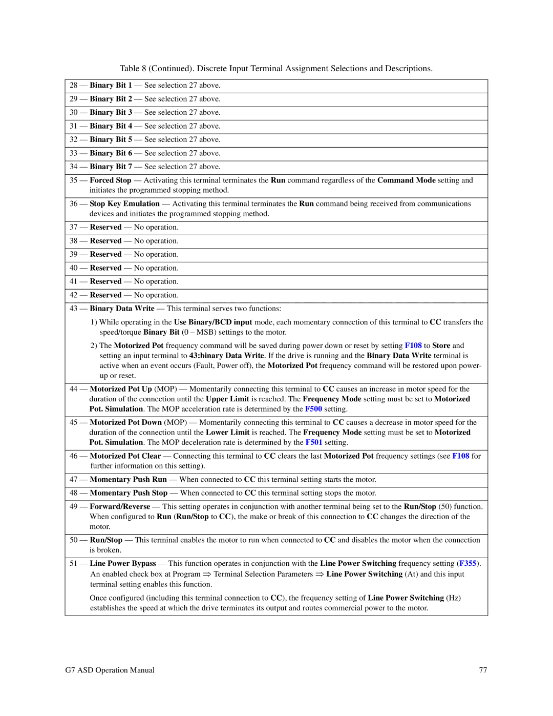
Table 8 (Continued). Discrete Input Terminal Assignment Selections and Descriptions.
28 — Binary Bit 1 — See selection 27 above.
29 — Binary Bit 2 — See selection 27 above.
30 — Binary Bit 3 — See selection 27 above.
31 — Binary Bit 4 — See selection 27 above.
32 — Binary Bit 5 — See selection 27 above.
33 — Binary Bit 6 — See selection 27 above.
34 — Binary Bit 7 — See selection 27 above.
35 — Forced Stop — Activating this terminal terminates the Run command regardless of the Command Mode setting and initiates the programmed stopping method.
36 — Stop Key Emulation — Activating this terminal terminates the Run command being received from communications devices and initiates the programmed stopping method.
37 — Reserved — No operation.
38 — Reserved — No operation.
39 — Reserved — No operation.
40 — Reserved — No operation.
41 — Reserved — No operation.
42 — Reserved — No operation.
43 — Binary Data Write — This terminal serves two functions:
1)While operating in the Use Binary/BCD input mode, each momentary connection of this terminal to CC transfers the speed/torque Binary Bit (0 – MSB) settings to the motor.
2)The Motorized Pot frequency command will be saved during power down or reset by setting F108 to Store and setting an input terminal to 43:binary Data Write. If the drive is running and the Binary Data Write terminal is active when an event occurs (Fault, Power off), the Motorized Pot frequency command will be restored upon power- up or reset.
44 — Motorized Pot Up (MOP) — Momentarily connecting this terminal to CC causes an increase in motor speed for the duration of the connection until the Upper Limit is reached. The Frequency Mode setting must be set to Motorized Pot. Simulation. The MOP acceleration rate is determined by the F500 setting.
45 — Motorized Pot Down (MOP) — Momentarily connecting this terminal to CC causes a decrease in motor speed for the duration of the connection until the Lower Limit is reached. The Frequency Mode setting must be set to Motorized Pot. Simulation. The MOP deceleration rate is determined by the F501 setting.
46 — Motorized Pot Clear — Connecting this terminal to CC clears the last Motorized Pot frequency settings (see F108 for further information on this setting).
47 — Momentary Push Run — When connected to CC this terminal setting starts the motor.
48 — Momentary Push Stop — When connected to CC this terminal setting stops the motor.
49 — Forward/Reverse — This setting operates in conjunction with another terminal being set to the Run/Stop (50) function. When configured to Run (Run/Stop to CC), the make or break of this connection to CC changes the direction of the motor.
50 — Run/Stop — This terminal enables the motor to run when connected to CC and disables the motor when the connection is broken.
51 — Line Power Bypass — This function operates in conjunction with the Line Power Switching frequency setting (F355). An enabled check box at Program ⇒ Terminal Selection Parameters ⇒ Line Power Switching (At) and this input terminal setting enables this function.
Once configured (including this terminal connection to CC), the frequency setting of Line Power Switching (Hz) establishes the speed at which the drive terminates its output and routes commercial power to the motor.
G7 ASD Operation Manual | 77 |