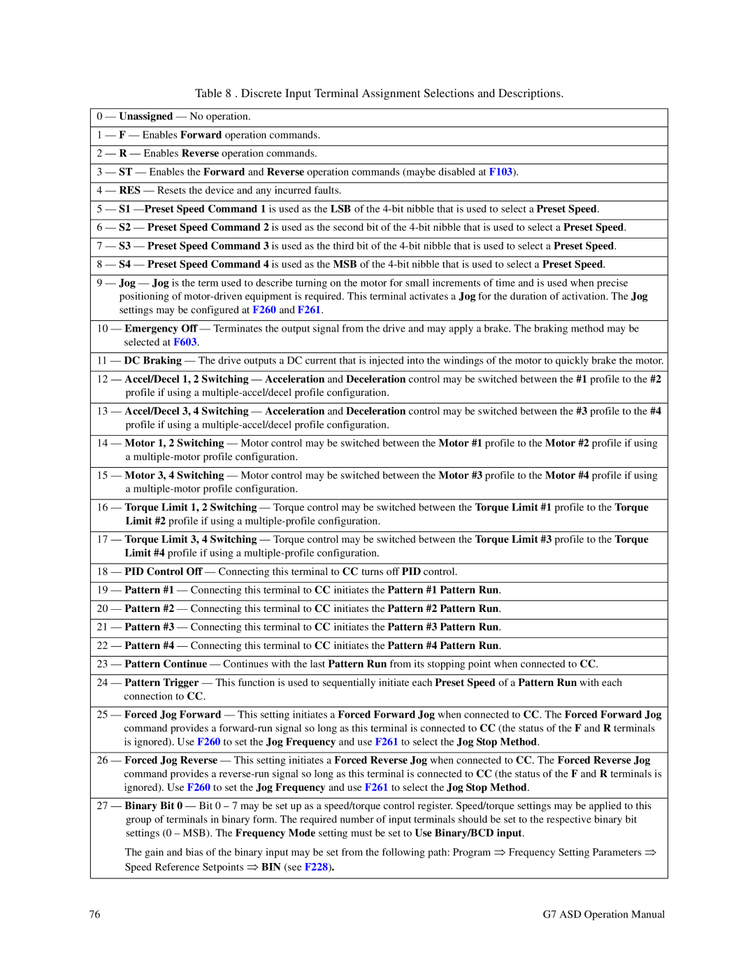
Table 8 . Discrete Input Terminal Assignment Selections and Descriptions.
0 — Unassigned — No operation.
1 — F — Enables Forward operation commands.
2 — R — Enables Reverse operation commands.
3 — ST — Enables the Forward and Reverse operation commands (maybe disabled at F103).
4 — RES — Resets the device and any incurred faults.
5 — S1
6 — S2 — Preset Speed Command 2 is used as the second bit of the
7 — S3 — Preset Speed Command 3 is used as the third bit of the
8 — S4 — Preset Speed Command 4 is used as the MSB of the
9 — Jog — Jog is the term used to describe turning on the motor for small increments of time and is used when precise positioning of
10 — Emergency Off — Terminates the output signal from the drive and may apply a brake. The braking method may be selected at F603.
11 — DC Braking — The drive outputs a DC current that is injected into the windings of the motor to quickly brake the motor.
12 — Accel/Decel 1, 2 Switching — Acceleration and Deceleration control may be switched between the #1 profile to the #2 profile if using a
13 — Accel/Decel 3, 4 Switching — Acceleration and Deceleration control may be switched between the #3 profile to the #4 profile if using a
14 — Motor 1, 2 Switching — Motor control may be switched between the Motor #1 profile to the Motor #2 profile if using a
15 — Motor 3, 4 Switching — Motor control may be switched between the Motor #3 profile to the Motor #4 profile if using a
16 — Torque Limit 1, 2 Switching — Torque control may be switched between the Torque Limit #1 profile to the Torque Limit #2 profile if using a
17 — Torque Limit 3, 4 Switching — Torque control may be switched between the Torque Limit #3 profile to the Torque Limit #4 profile if using a
18 — PID Control Off — Connecting this terminal to CC turns off PID control.
19 — Pattern #1 — Connecting this terminal to CC initiates the Pattern #1 Pattern Run.
20 — Pattern #2 — Connecting this terminal to CC initiates the Pattern #2 Pattern Run.
21 — Pattern #3 — Connecting this terminal to CC initiates the Pattern #3 Pattern Run.
22 — Pattern #4 — Connecting this terminal to CC initiates the Pattern #4 Pattern Run.
23 — Pattern Continue — Continues with the last Pattern Run from its stopping point when connected to CC.
24 — Pattern Trigger — This function is used to sequentially initiate each Preset Speed of a Pattern Run with each connection to CC.
25 — Forced Jog Forward — This setting initiates a Forced Forward Jog when connected to CC. The Forced Forward Jog command provides a
26 — Forced Jog Reverse — This setting initiates a Forced Reverse Jog when connected to CC. The Forced Reverse Jog command provides a
27 — Binary Bit 0 — Bit 0 – 7 may be set up as a speed/torque control register. Speed/torque settings may be applied to this group of terminals in binary form. The required number of input terminals should be set to the respective binary bit settings (0 – MSB). The Frequency Mode setting must be set to Use Binary/BCD input.
The gain and bias of the binary input may be set from the following path: Program ⇒ Frequency Setting Parameters ⇒ Speed Reference Setpoints ⇒ BIN (see F228).
76 | G7 ASD Operation Manual |