Cable/Terminal Specifications
Installation should conform to the 2002 National Electrical Code Article 110 (NEC) (Requirements for Electrical Installations), all regulations of the Occupational Safety and Health Administration, and any other applicable national, regional, or industry codes and standards.
Note: The following ratings are guidelines and shall not be the sole determining factor of the lug or wire size used with the ASD.
Note: Cable/Terminal specifications are based on the rated current of the ASD and Do Not include the 10% Service Factor.
For further installation information see the section titled Installation and Connections on pg. 17.
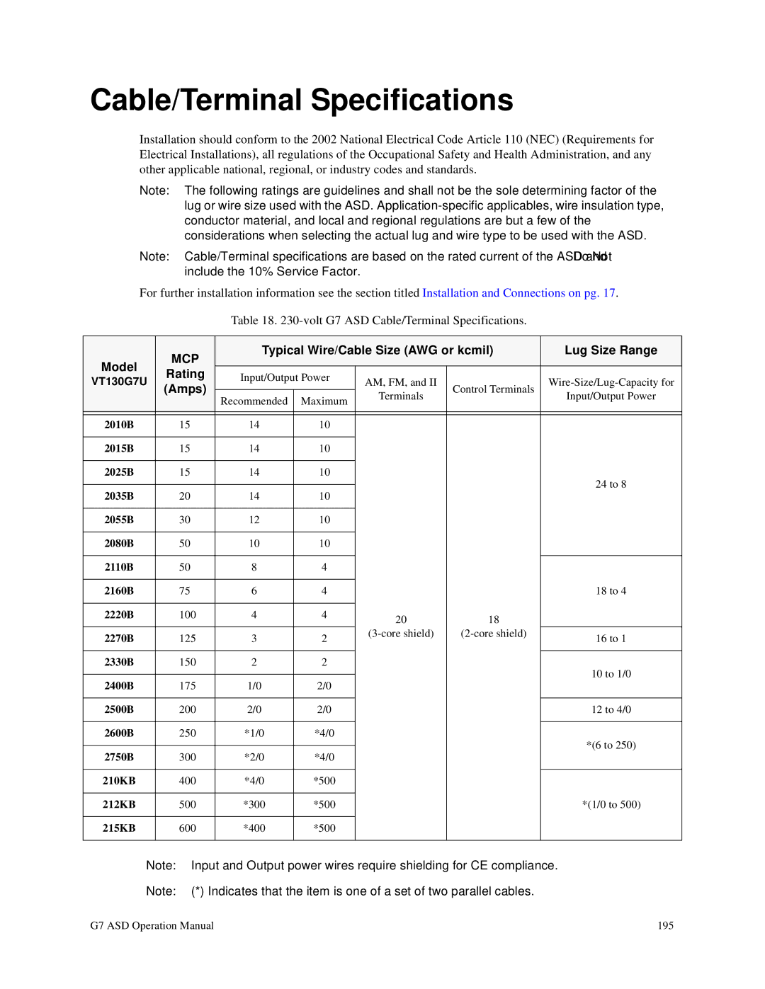
Table 18.
| MCP | Typical Wire/Cable Size (AWG or kcmil) | Lug Size Range | |||
Model |
|
|
|
|
| |
Rating | Input/Output Power |
|
|
| ||
VT130G7U | AM, FM, and II |
| ||||
(Amps) |
|
| Control Terminals | |||
| Recommended | Maximum | Terminals | Input/Output Power | ||
|
|
| ||||
|
|
|
|
| ||
|
|
|
|
|
|
|
|
|
|
|
|
|
|
2010B | 15 | 14 | 10 |
|
|
|
|
|
|
|
|
|
|
2015B | 15 | 14 | 10 |
|
|
|
|
|
|
|
|
|
|
2025B | 15 | 14 | 10 |
|
| 24 to 8 |
|
|
|
|
|
| |
2035B | 20 | 14 | 10 |
|
| |
|
|
| ||||
|
|
|
|
|
|
|
2055B | 30 | 12 | 10 |
|
|
|
|
|
|
|
|
|
|
2080B | 50 | 10 | 10 |
|
|
|
|
|
|
|
|
|
|
2110B | 50 | 8 | 4 |
|
|
|
|
|
|
|
|
|
|
2160B | 75 | 6 | 4 |
|
| 18 to 4 |
|
|
|
|
|
|
|
2220B | 100 | 4 | 4 | 20 | 18 |
|
|
|
|
|
| ||
2270B | 125 | 3 | 2 | 16 to 1 | ||
|
| |||||
|
|
|
|
|
|
|
2330B | 150 | 2 | 2 |
|
| 10 to 1/0 |
|
|
|
|
|
| |
2400B | 175 | 1/0 | 2/0 |
|
| |
|
|
| ||||
|
|
|
|
|
|
|
2500B | 200 | 2/0 | 2/0 |
|
| 12 to 4/0 |
|
|
|
|
|
|
|
2600B | 250 | *1/0 | *4/0 |
|
| *(6 to 250) |
|
|
|
|
|
| |
2750B | 300 | *2/0 | *4/0 |
|
| |
|
|
| ||||
|
|
|
|
|
|
|
210KB | 400 | *4/0 | *500 |
|
|
|
|
|
|
|
|
|
|
212KB | 500 | *300 | *500 |
|
| *(1/0 to 500) |
|
|
|
|
|
|
|
215KB | 600 | *400 | *500 |
|
|
|
|
|
|
|
|
|
|
Note: Input and Output power wires require shielding for CE compliance.
Note: (*) Indicates that the item is one of a set of two parallel cables.
G7 ASD Operation Manual | 195 |