8-6 Troubleshooting
DISK ACCESS Lamp
The DISK ACCESS lamp indicates the state of hard disks in the
When the DISK ACCESS lamp is lit in amber, it indicates that a hard disk error occurred. To identify a failed hard disk, see the lamps provided for each hard disk.
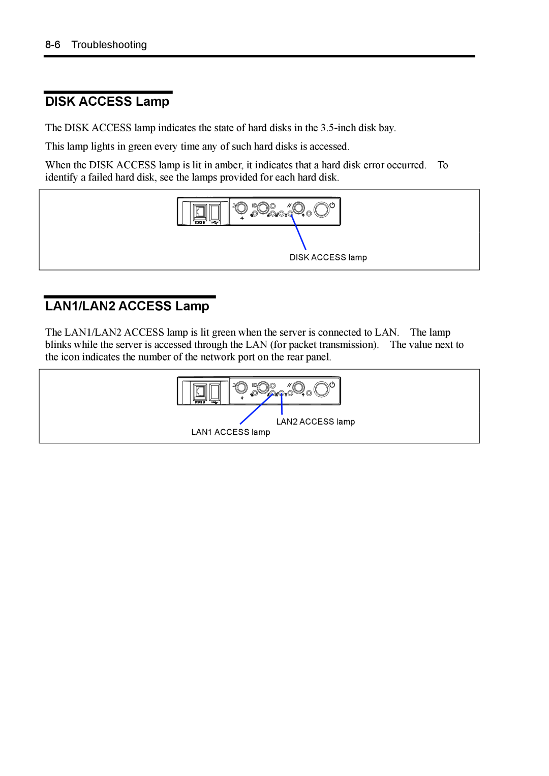
DISK ACCESS lamp
LAN1/LAN2 ACCESS Lamp
The LAN1/LAN2 ACCESS lamp is lit green when the server is connected to LAN. The lamp blinks while the server is accessed through the LAN (for packet transmission). The value next to the icon indicates the number of the network port on the rear panel.
LAN2 ACCESS lamp
LAN1 ACCESS lamp