General Description
Front View (with Front Bezel Removed)
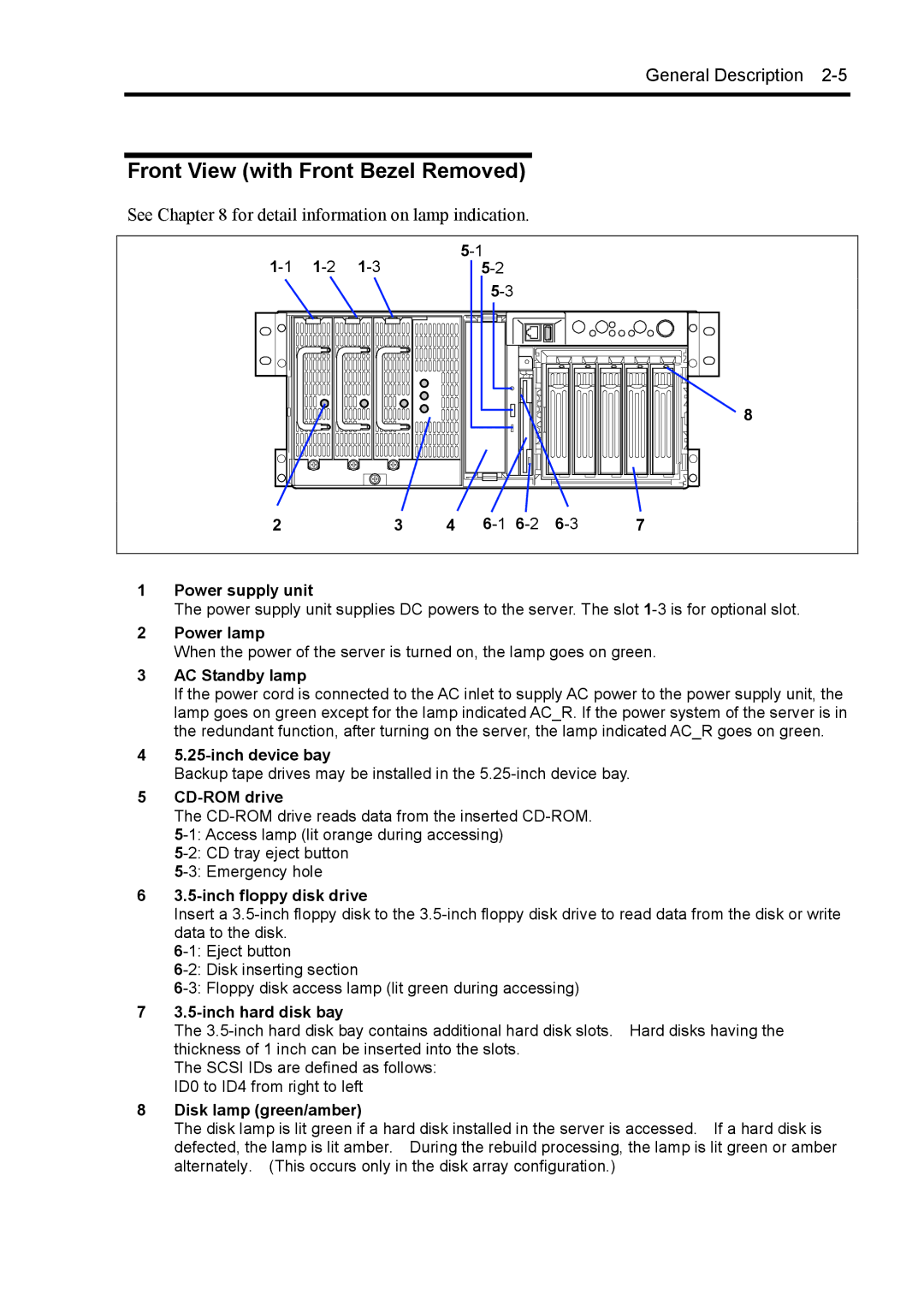
See Chapter 8 for detail information on lamp indication.
|
|
| |||
|
|
| |||
|
|
|
|
| |
|
|
|
|
| 8 |
2 |
| 3 | 4 | 7 |
1Power supply unit
The power supply unit supplies DC powers to the server. The slot
2Power lamp
When the power of the server is turned on, the lamp goes on green.
3AC Standby lamp
If the power cord is connected to the AC inlet to supply AC power to the power supply unit, the lamp goes on green except for the lamp indicated AC_R. If the power system of the server is in the redundant function, after turning on the server, the lamp indicated AC_R goes on green.
4
Backup tape drives may be installed in the
5CD-ROM drive
The
63.5-inch floppy disk drive
Insert a
73.5-inch hard disk bay
The
The SCSI IDs are defined as follows: ID0 to ID4 from right to left
8Disk lamp (green/amber)
The disk lamp is lit green if a hard disk installed in the server is accessed. If a hard disk is defected, the lamp is lit amber. During the rebuild processing, the lamp is lit green or amber alternately. (This occurs only in the disk array configuration.)