Front View (Switches and Lamps)
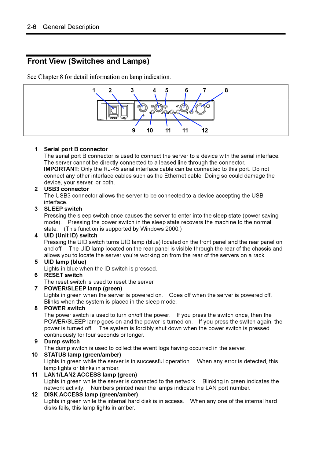
See Chapter 8 for detail information on lamp indication.
1 | 2 | 3 | 4 | 5 | 6 | 7 | 8 | ||
|
|
|
|
|
|
|
|
|
|
|
|
|
|
|
|
|
|
|
|
|
|
|
|
|
|
|
|
|
|
|
|
|
|
|
|
|
|
|
|
9 | 10 | 11 | 11 | 12 |
1Serial port B connector
The serial port B connector is used to connect the server to a device with the serial interface. The server cannot be directly connected to a leased line through the connector. IMPORTANT: Only the
2USB3 connector
The USB3 connector allows the server to be connected to a device accepting the USB interface.
3SLEEP switch
Pressing the sleep switch once causes the server to enter into the sleep state (power saving mode). Pressing the power switch in the sleep state recovers the machine to the normal state. (This function is supported by Windows 2000.)
4UID (Unit ID) switch
Pressing the UID switch turns UID lamp (blue) located on the front panel and the rear panel on and off. The UID lamp located on the rear panel is visible through the rear of the chassis and allows you to locate the server you're working on from the rear of the servers on a rack.
5UID lamp (blue)
Lights in blue when the ID switch is pressed.
6RESET switch
The reset switch is used to reset the server.
7POWER/SLEEP lamp (green)
Lights in green when the server is powered on. Goes off when the server is powered off. Blinks when the system is placed in the sleep mode.
8POWER switch
The power switch is used to turn on/off the power. If you press the switch once, then the POWER/SLEEP lamp goes on and the power is turned on. If you press the switch again, the power is turned off. The system is forcibly shut down when the power switch is pressed continuously for four seconds or longer.
9Dump switch
The dump switch is used to collect the event logs having occurred in the server.
10STATUS lamp (green/amber)
Lights in green while the server is in successful operation. When any error is detected, this lamp lights or blinks in amber.
11LAN1/LAN2 ACCESS lamp (green)
Lights in green while the server is connected to the network. Blinking in green indicates the network activity. Numbers printed near the lamps indicate the LAN port number.
12DISK ACCESS lamp (green/amber)
Lights in green while the internal hard disk is in access. When any one of the internal hard disks fails, this lamp lights in amber.