4-46 Configuring Your Server
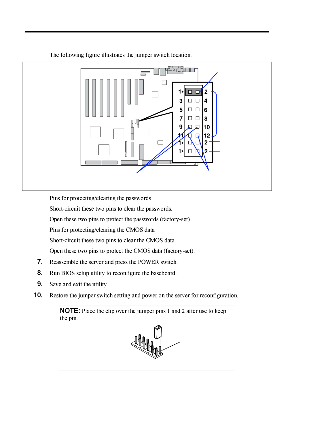
The following figure illustrates the jumper switch location.
Use the clip over pins 1 and 2.
JP4
JP5
JP6
Pins for protecting/clearing
Pins for protecting/clearingthe CMOS data. the passwords.
Pins for protecting/clearing the passwords
Open these two pins to protect the passwords
Pins for protecting/clearing the CMOS data
Open these two pins to protect the CMOS data
7.Reassemble the server and press the POWER switch.
8.Run BIOS setup utility to reconfigure the baseboard.
9.Save and exit the utility.
10.Restore the jumper switch setting and power on the server for reconfiguration.
NOTE: Place the clip over the jumper pins 1 and 2 after use to keep the pin.
Pins 1 and 2.
