Manuals
/
NEC
/
Computer Equipment
/
Server
NEC
140Rc-4
manual
Install the front bezel Now the installation is completed
Models:
140Rc-4
1
93
400
400
Download
400 pages
61.79 Kb
90
91
92
93
94
95
96
97
Troubleshooting
Specification
Install
Error messages
Empty Bus Default Speed
Connecting Peripheral Devices
Maintenance
Configuring Your Server
Setting for Solving Problems
Resetting the Server
Page 93
Image 93
Setting Up Your Server
3-21
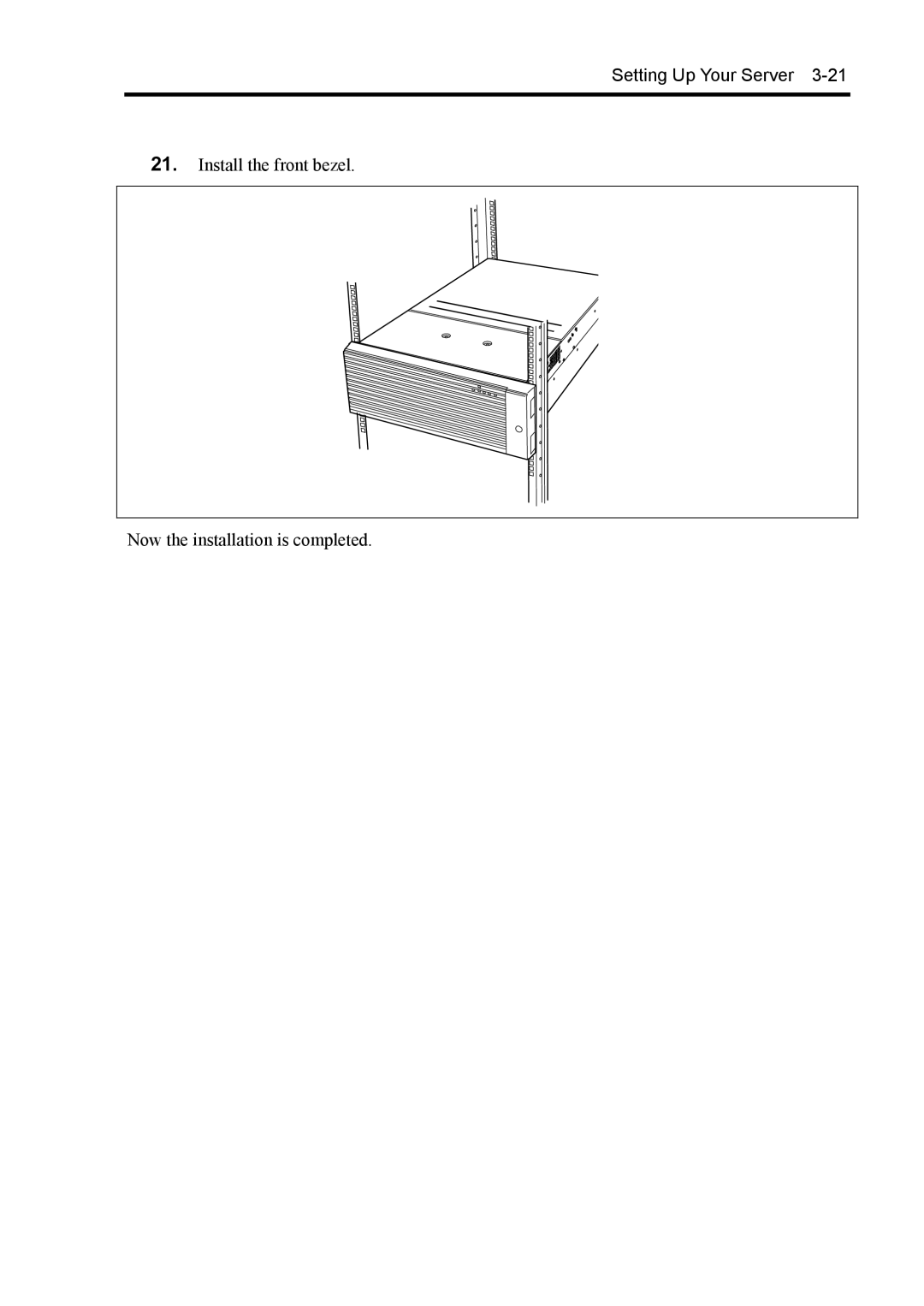
21.
Install the front bezel.
Now the installation is completed.
Page 92
Page 94
Page 93
Image 93
Page 92
Page 94
Contents
NEC Express5800/140Rc-4 Users Guide
Proprietary Notice and Liability Disclaimer
Safety Indications
Safety Indications by Color of the Parts
Symbols Used in this Users Guide and Warning Labels
Prohibited Actions
Mandatory Action
CE Statement Bsmi Statement
Momentary voltage drop prevention
Trademarks
Preface
About this Users Guide
How to Use This Users Guide
Text Conventions
Package
This page is intentionally left blank
Contents
Post
NEC Expressbuilder
Installing the Operating System with Express Setup
Viii
Other Precautions
Specifications
Appendix a
Appendix B
Hardware Software
Chapter
Attached to the CPU access cover
General
Safety Notes
Page
Page
Power Supply and Power Cord Use
Installation, Relocation, Storage, and Connection
Page
Do not disassemble, repair, or alter the server
Cleaning and Working with Internal Devices
Page
During Operation
For Proper Operation
Page
Transfer to Third Party
NEC Express server
Provided software
Disposal of the Server
Consumables
User Support
When Having Your Server Repaired
Advice for Health
This page is intentionally left blank
General Description
Overview
Front access cover
Rear access cover
Top View
Front View
Front bezel
Key hole
Front View with Front Bezel Removed
Front View Switches and Lamps
Rear View
Mouse connector
Keyboard connector
Serial port a connector
Monitor connector
Internal View
Electronics Bay
Intelligent Chassis Management Bus Icmb connector
Baseboard
1-2 1-1 2 Additional PCI board slots 8slots
Processor Board
Processor board interface connector
Memory Board
Dimm socket
Standard Features
Peripheral Bays
Power Supplies
Online Sparing Memory Feature
Memory Mirroring Feature
System Cooling
SAF-TE Logic
Processor
System Board Features
Dimm Memory
Onboard Video
Network Interface Controllers
Scsi Controller
System Board Management Controller BMC
Degradation Feature
Remote Power-On Feature Wake On LAN
AC-LINK Feature
Software Locks via the System Setup Utility
Security
Security with Mechanical Locks and Monitoring
NEC Expressbuilder
Off-line Maintenance Utility
System Diagnostic Utility
NEC Management Workstation Application NEC MWA
Using Your Server
Installing or Removing the Front Bezel
Front Bezel
Power On
Power Switch
Post
Post Flow
Displayed message may vary depending on the device status
„ F2
„ Esc
„ F4
„ F12
Power Off
Post Error Messages
Sleep Switch
Floppy Disk Drive
Write-protect switch Write Write disable enable
CD-ROM Drive
CD-ROM
Emergency hole
General Description
Setting Up Your Server
Follow the flowchart below to set up the server
Setup Flow
Installation
Installation of Rack
Selecting a Site
Setting Up Your Server
Unpacking the System
Assembling the RACK-MOUNT System
Checking Components
ESD Precaution
Qty Remarks
Required Tools
Installation Procedure
Inner rail Slide rail assembly Release lever
Handle L
Screw B
Screws
Setting Up Your Server
Release lever
Cable arm
Mount face
Arm bracket
Setting Up Your Server
Screws C and Washers a
Install the front bezel Now the installation is completed
More than one person should remove the server from the rack
Removal Procedure
Unlock Lock
Connecting Peripheral Devices
Front
Connection to Serial Ports
Connection between the RJ-45 Serial Port and a Modem
Connection between the RJ-45 Serial Port and a UPS
DTE
Setting Up Your Server
JP25
Only for LVD
Connection to External Scsi Devices
Connect the provided power cord to the server
Connecting Power Cord
Example
Turning on the Server
Setting Up Your Server
Installing Operating System
Installing Utilities
Making Backup Copies of System Information
This page is intentionally left blank
System Bios ~ Setup ~
Configuring Your Server
Starting Setup Utility
Enter
Description on On-Screen Items and Key Usage
Esc
F10
Configuration Examples
Boot
Link with Management Software
Memory
To check the installed memory Dimm board status
CPU
Security
External Devices
Internal Devices
Saving the Configuration Data
Code Board name Setting Value
PCI Hot Plug
Main
Menu and Parameter Descriptions
MM/DD/YYYY
Option Parameter Description Your Setting
Cpuid
Processor Settings
CD-ROM
Primary IDE Master/Primary IDE Slave
Fpio 3/DMA Fpio 4/DMA
Advanced
1KB
Memory Configuration
PCI Configuration
PHP
Hot-plug PCI Control
Empty Bus Default Speed
Embedded SCSI/Embedded NIC/Embedded Video Controller
PCI Slot 1 PCI Slot
Device Configuration
EPP
Advanced Chipset Control
PCI Device
Selectable only when User Password is registered
CTRL+ALT+
Server
BMC IRQ
Configuring Your Server
System Management
VT-UTF8
Console Redirection
Boot
Exit
Exit Saving Changes
Exit Discarding Changes
Load Custom Defaults
Load Setup Defaults
Save Custom Defaults
Discard Changes
Using SCSISelect Utility
Scsi Bios ~ SCSISelect ~
Running the Utility
Configuring Scsi Controller on Baseboard
Exiting the Utility
Configure/View Host Adapter Settings
Scsi Bus Interface Definitions
Menu item Parameter Description
„ Boot Device Configuration
Additional Options
Submenu item Parameter Description
„ Scsi Device Configuration
Asyn
Advanced Configuration
„ Advanced Configuration
Baseboard has no hard disks connected, there
Submenu item Description
Scsi Disk Utilities
Configuring Scsi Controller on Optional Board
Configuring Baseboard Jumpers
Following figure illustrates the jumper switch location
Installing the Operating System with Express Setup
About Express Setup
NEC Expressbuilder
Installing Optional Mass Storage Driver
Installation Notice
Bios Specification
Supported OS on this model
Windows Server
Installing on the Mirrored Volume
Creating Partition Size
Agree Software License Agreement Restart
Flow of Setup
Installing the Windows Server
Using Blank disk
Using the specified Configuration Diskette
Installing the Operating System with Express Setup
Installing the Operating System with Express Setup
PROSet
Installing and Setting Device Drivers
Network Driver
Optional Network Board Driver N8104-80/86/103/111/113
Installing Scsi Controller Driver
Memory Dump Debug Information
Setting for Solving Problems
Installing the Operating System with Express Setup
Windows Dr. Watson
Network Monitor
Installing Maintenance Utilities
Updating the System
Making Backup Copies of System Information
Exceptional Setup
Microsoft Windows
Windows
Creating Partition Size
Disk Configuration Concerning the area displayed as Maintep
Insert SP CD-ROM
Installing the Windows
Using the specified Configuration Diskette
Installing the Operating System with Express Setup
Installing the Operating System with Express Setup
Installing and Setting Device Drivers
Network Driver
Graphics Accelerator Driver
Optional Network Board Driver
Installing Scsi Controller Driver
Setting for Solving Problems
Installing the Operating System with Express Setup
Windows 2000 Dr. Watson
Installing Maintenance Utilities
Updating the System Applying Service Pack
Exceptional Setup
This page is intentionally left blank
Installing and Using Utilities
NEC Expressbuilder
Installing and Using Utilities
Starting NEC Expressbuilder
NEC Expressbuilder for DOS-Based with Local Console
Tools
Express Setup
Installing and Using Utilities
Installing and Using Utilities
Fdisk
Installing and Using Utilities
Starting
NEC Expressbuilder for DOS-based with Remote Console
Main Menu
Setup
NEC Expressbuilder for Windows-Based Master Control Menu
Installing Configuration Diskette Creator
Configuration Diskette Creator
Installing and Using Utilities
Creating Configuration Diskette
Installing and Using Utilities
Installing Optional Mass Storage Driver
NEC Esmpro
Functions and Features
Precautions
NEC MWA
Servers to be Remotely Managed by MWA
Through the management PC via LAN
Installing and Using Utilities
Installing and Using Utilities
Through the management PC with direct connection
Installing and Using Utilities
Major Functions
Power Console Plus
Components
Installing and Using Utilities
Operating Environment
Server Setup
Management PC Setup
Making Backup Copies
Maintenance
Cleaning
Cleaning the Server
Cleaning the Interior
Cleaning the Keyboard/Mouse
Cleaning CD-ROM
Test Items
System Diagnostics
Starting and Ending the System Diagnostics
Guide line Test window Test result
Test Result
RELOCATING/STORING the Server
Follow the procedure below to relocate or store the server
Maintenance
Troubleshooting
Example
System Viewers
Lamps
POWER/SLEEP Lamp
Status lamp Description Action Indication
Status Lamp
Troubleshooting
LAN1/LAN2 Access Lamp
Disk Access Lamp
UID Lamp
Access Lamps
Hard Disk Drive Lamp Disk Lamp
AC Standby Lamp
Power Lamp
LAN Connector Lamps
PCI Slot Power Lamp
PCI Slot Fault Lamp
PCI Slot Lamps
FAN Fault Lamps
Error Messages after Power-on
Error Messages
Error Error message Recommended Action Code
Post Error Messages
Troubleshooting
Contact you service representative to add an
0BDA
Troubleshooting
„ Processors CPUs
Beep code Description Recommended action
Beep Codes
Problems with Server
Solving Problems
Fail to power on the server
No screen display appears with beep
Post fails to complete
Fail to power of the server / Sleep switch is disabled
Troubleshooting
Keyboard or mouse fails to operate
Fail to access read or write to the floppy disk
Fail to access the hard disk
Fail to access to the CD-ROM
Cannot install the operating system correctly
Fail to access the internal or external Scsi devices
Cannot turn the power OFF at the blue screen
Fail to start the OS
OS presents unstable operation
System displays the message below and fails to log
Server is not found on the network
Event logs in using Snmp Service in Windows Server
PCI hot-plug fails
PCI board is not recognized
Message Cause and Remedy
Problems with NEC Expressbuilder
Problems with Express Setup
For Windows
Complete appears on the Role of Computer screen
Entered the incorrect Product ID/CD key
Complete does not appear on Role of Computer screen
Unable to specify the details of Network adapter
Error Message during Disk Array Configuration
Problems with Master Control Menu
Master control menu fails to appear
Problems with Configuration Diskette Creator
Point to Point tunneling protocol cannot be set
Details of a network adapter cannot be set
Collecting Event LOG
Collect Configuration Information
Collecting DR. Watson Diagnostic Information
Memory Dump
Preparing for Memory Dumping
Saving the Dump File
Recovery for Windows
Troubleshooting
OFF-LINE Maintenance Utility
Starting the Off-line Maintenance Utility
Features of Off-line Maintenance Utility
Forced Shutdown
Resetting the Server
This page is intentionally left blank
Upgrading Your Server
Upgrading Your Server
ANTI-STATIC Measures
Preparing for Installation and Removal
Tools and Supplies Needed
Hard Disk Drive
Device Installation or Removal Procedure
Installation
Hook Frame to hang the hook
Removal
Upgrading Your Server
Power Supply Unit
Upgrading Your Server
Replacing a Failing Power Supply Unit
Upgrading Your Server
Server ~ Extending from the Rack Cabinet~
Release lever
Front Access Cover
Inch Peripheral Device
Installation Considerations
„ Scsi device
„ IDE device
Upgrading Your Server
Ultra 320 B connector Interface cable Device
Removal
Rear Access Cover
CPU Access Cover
PCI Board
RAID Controller Considerations
List of Optional Devices and their Available Slots
Onboard LAN Controller Considerations
Hot-plug
Non-hot-plug PCI Boards
Installation
Lock
Removal
Hot-plug PCI Board
„ PCI boards installed on the same bus
„ No boards installed in the same bus
„ PCI slot Power lamp green
„ PCI slot Fault lamp amber
Hot Add
Upgrading Your Server
Upgrading Your Server
Hot Remove
Upgrading Your Server
Upgrading Your Server
Tab Lock for long card
Hot Replace
Upgrading Your Server
Upgrading Your Server
Tab Lock for long card
Upgrading Your Server
Upgrading Your Server
To install or remove the DIMM, remove the memory board first
Installation
Dimm
Installation
Upgrading Your Server
Removal
Memory Mirroring Feature
Memory Mirroring / Online Spare Memory Feature
Dimm group #1 Dimm group #2 Dimm group #3
Online Spare Memory
Online Spare Memory was not ready
Processor Board Air Duct
Move the AC inlet into place and attach it using the screw
Processor Board
Installation
Processor CPU
Retention
Pin marks
Upgrading Your Server
Removal
IDE Interface
Cable Connection
Baseboard
Scsi Interface
Disk Array Controller
Disk array configuration of built-in disks
Upgrading Your Server
Upgrading Your Server
Disk array configuration of disk expansion units
External Scsi Cable
Blank cover
Serial Interface
Upgrading Your Server
Upgrading Your Server
This page is intentionally left blank
Appendix a
Specifications
Server Management Software
Transfer Rate of the On-board LAN Controller
Floppy Disk
Floppy disk type
Other Precautions
Other Precautions B-3
Tape Media
CD-ROM
Keyboard
Other Precautions B-5
Mouse
Peripheral Device Controller
Interrupt Request
Menu Option Interrupt
Pirq and PCI Device
Address Chip in Use
Port Address
CD6
Installing Service Pack
Disk Configuration Concerning the area displayed as Maintep
Updating System
MO Device
Media such as DAT
Partition Size
Creating Windows Server 2003 OEM-DISK for NEC
Installing Windows Server
Installing Windows Server
Following message is displayed
Windows Server 2003 Clean Installation
Procedure for License Authentication
Upgrade installation
Installing Windows Server
PROSet
Driver Installation and Advanced Settings
Network Driver
Installing Scsi Controller Driver
Re-install the Network Driver
Setting for Collecting Memory Dump Debug Information
Appendix E
Installing Windows
Installing Windows 2000 E-3
Creating Windows 2000 OEM-DISK for NEC Expressbuilder
Preparations for Installation
Installing Windows 2000 E-5
Windows 2000 Clean Installation
Installing Windows 2000 E-7
Driver Installation and Advanced Settings
Installing Windows 2000 E-9
Re-install the Network Driver
Graphics Accelerator Driver
Setting for Collecting Memory Dump Debug Information
Hardware
Appendix F
Product Configuration Record Table
† Hpfs † Ntfs
Software
This page is intentionally left blank
Top
Page
Image
Contents