Communication Server 1000E
Installation and Configuration
Page
August
Revision history
September
July
4 of 488 Revision history Standard 4.00 September
Contents
Telephones Rack-mounting the components
Installing software on the CS 1000E
Installing and configuring the Signaling Server software
Installing software on an MG 1000E Small System Controller
Connecting a Terminal Server
Installing and cross-connecting a trunk card
Installing the Main Distribution Frame
Installing and configuring IP Phones
Basic system telephony configuration
Implementation summary
16 of 488 Contents
List of Procedures
18 of 488 List of Procedures
List of Procedures Page 19
20 of 488 List of Procedures
List of Procedures Page 21
22 of 488 List of Procedures
List of Procedures Page 23
24 of 488 List of Procedures
List of Procedures Page 25
26 of 488 List of Procedures
List of Procedures Page 27
28 of 488 List of Procedures Standard 4.00 September
Subject
About this document
Following NTPs are referenced in this document
Applicable systems
Conventions
Related information
CD-ROM
32 of 488 About this document Standard 4.00 September
Introduction
Safety instructions
Contents
Handling circuit cards
Lifting system equipment
Using telephones
Installing telephones
36 of 488 Safety instructions
Installation summary
List of required installation tasks Part 1 Task Go to
Installation tasks
List of required installation tasks Part 2 Task Go to
40 of 488 Installation summary Standard 4.00 September
System components
CS 1000E Call Server
CS 1000E Core Call Server top view
CS 1000E Core Call Server front view
Backup and restore enhancements
Signaling Server
New backup rules
NTDU27
Network Routing Service Element Manager web server
Signaling Server profile Part 2 Property Description
Server Installation and Configuration
Connectors on the front of the Signaling Server
CD-ROMand floppy drives Maintenance port
Media Card profile Part 1 Property Description
Connectors at the back of the Signaling Server
Media Card
Media Card profile Part 2 Property Description
Media Card
Media Gateway
Media gateway is shown in on page 52 and described on
NTDU14
Pair Cable Connectors on the Media Gateway
Media Gateway profile Part 1 Property Description
Media Gateway profile Part 2 Property Description
Media Gateway profile Part 3 Property Description
Connectors at the back of the Media Gateway
Front of the Media Gateway
NTDU15
Media Gateway Expander
Media Gateway Expander
Media Gateway Expander profile Part 1 Property Description
Media Gateway Expander profile Part 2 Property Description
Media Gateway Expander profile Part 3 Property Description
Order Code Description Qty
Connectors at the back of the Media Gateway Expander
Inch Rack Mount Kit
BayStack 470 Switch profile Part 1 Property Description
BayStack 470 Switch
Ethernet switch
BayStack 470 Switch profile Part 2 Property Description
MRV Terminal Server
BayStack 460 Layer 2 switch
Power over LAN unit
64 of 488 System components
NTVW00AB
Inch rack
System cables
MRV IR-8020M Terminal Server profile Property Description
66 of 488 System components
NTBK48AA
CS 1000E cables Part 1
NTTK18AB
NTDK95AA
NTTK34AA
NTTK14AB
Miscellaneous components Order Code Description Purpose
Miscellaneous system components
Uninterruptible Power Supply
Telephones
72 of 488 Telephones
Rack-mounting the components
Lifting system components
Weight of CS 1000E system components Component Lbs
Guidelines for component placement in a rack
Items required
Rack-mounting a CS 1000E Call Server
Rack-mounting a Media Gateway or Media Gateway Expander
Procedure Rack-mounting a CS 1000E Call Server
CS 1000E Call Server with installed ear brackets
End of Procedure
Procedure Removing the cover
Unlock the latches Unlock the cover End of Procedure
Guide bracket installed in a rack
Right ear bracket on a Media Gateway
Use two screws on each side to fasten the Media Gateway
Media Gateway installed in a rack
Signaling Server mounting accessories
Rack-mounting a Signaling Server
Procedure Preparing a Signaling Server for rack-mounting
Chassis support bracket
Left hinge mount Right hinge mount
Page
Grounding the Rack Installation
Disconnect AC Power
Installed rack-mount bracket
Main AC Power Disconnect
Rack-mounting the Signaling Server
Rack-mounting a Terminal Server
Rack-mounting a BayStack 470 Switch
Rack-mounting a BayStack 460 Power over Ethernet unit
Installing system grounds
Installing a ground bar
Procedure Installing an NTBK80 Ground Bar
Follow Procedure 6 to install a ground bar
Procedure Installing an NTDU6201 Ground Bar
Follow Procedure 7 to install an NTDU6201 Ground Bar
NTBK80 Ground Bar End of Procedure
Grounding a CS 1000E Call Server
Grounding a Signaling Server
96 of 488 Installing system grounds
Installing system grounds Page 97
Grounding a Media Gateway Expander
Follow Procedure 10 to ground a Media Gateway Expander
Procedure Grounding a Media Gateway Expander
Grounding other rack-mounted components
Installing system grounds Page 99
Grounding multiple pieces of equipment in a rack
Grounding equipment in the UK
Follow Procedure 11 to ground equipment in the UK
Procedure Grounding equipment in the UK
102 of 488 Installing system grounds Standard 4.00 September
This section contains information on the following topics
Connecting CS 1000E system components
Connecting Call Server 0 to Call Server
Procedure Connecting co-located Call Servers
Connecting co-located Call Servers
Connecting Campus Redundant Call Servers
Follow Procedure 12 to connect co-located Call Servers
Vlan 3 Elan
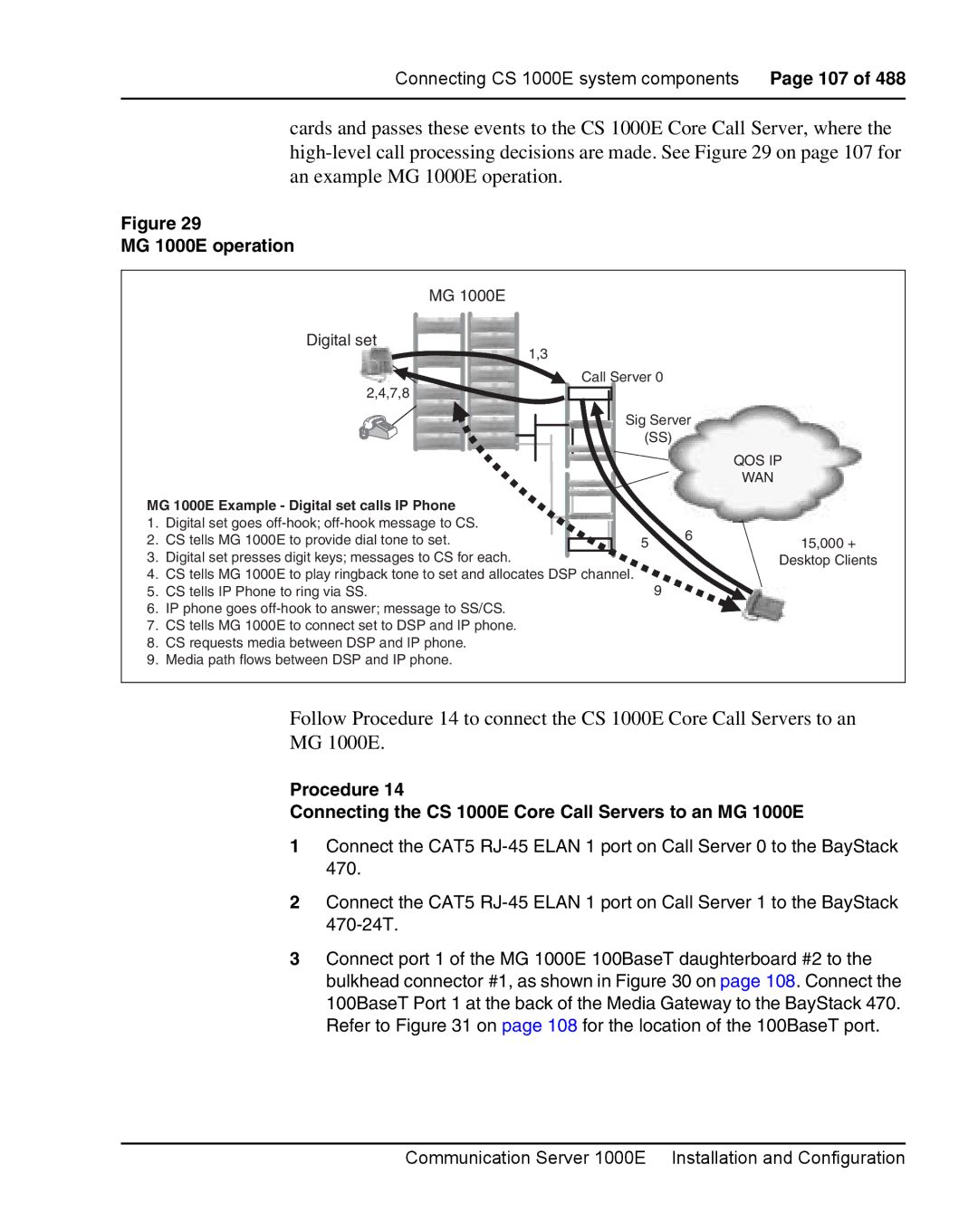
Connecting the CS 1000E Core Call Servers to an MG 1000E
Procedure Connecting Campus Redundant Call Servers
MG 1000E Digital set
MG 1000E operation
100BaseT ports
Dual Homed connection
HSP
Robust Data Network Topology
Procedure Connecting a Signaling Server to the Elan
Connecting a Signaling Server to the Elan subnet
Tlan Elan
Connecting a Signaling Server to the Tlan subnet
Signaling Server Elan subnet and Tlan subnet connectors
Procedure Connecting a Signaling Server to the Tlan subnet
Tlan RJ-45 Elan RJ-45
Shielded 50-pin to Serial/ELAN/TLAN adapter
Procedure Connecting a Media Card to the Elan subnet
Connecting a Media Card to the Elan subnet
Follow Procedure 19 to connect a Media Card to the Elan
Procedure Connecting a Media Card to the Tlan subnet
Connecting a Media Card to the Tlan subnet
Connecting a Media Gateway to a Media Gateway Expansion
Media Gateway and Media Gateway Expander connections
Page
Installing software on the CS 1000E
Procedure Installing the software on the Call Server
Installing the software
Installing software on the CS 1000E Page 121
122 of 488 Installing software on the CS 1000E
FAT
124 of 488 Installing software on the CS 1000E
Installing software on the CS 1000E Page 125
I N M E N U
Following keycode files are available on
System requests keycode validation
Install M E N U
Standard 4.00 September
Installing software on the CS 1000E Page 131
132 of 488 Installing software on the CS 1000E
SDL Installation Menu
Standard 4.00 September
Continue with database installation
Page
Install M E N U
At this point the system reloads and initializes
Procedure Verifying the installation database
Verify the installation database
Procedure Reconfiguring I/O ports and call registers
Reconfigure I/O ports and call registers
Test the Call Server
Install the software on the second Call Server
Procedure Testing the Call Server
Procedure Installing the software on the second Call Server
Stat CPU Get status of CPU and memory Exit the program
Procedure Making the system redundant
Verifying Call Server 0 is active
Make the system redundant
Stat Health Get status of CPU and memory Exit the program
144 of 488 Installing software on the CS 1000E
Installing software on the CS 1000E Page 145
Get status of MG 1000E Ipmg
Complete the CP PIV installation
Command parameter none
Procedure Testing Call Server
Command parameter core # with values of 0 or
Test database integrity
Stat CPU Get status of CPU and memory
Load program
Test redundancy
To Call Server
Switch call processing from Call Server
Procedure Switching call processing
End of Procedure Testing Call Server
Clear the displays on the Call Servers
Loss of Data
Perform a customer backup data dump installation release
Installation is now complete
Connecting MG 1000T system components
Pstn
MG 1000T Media Gateway operation
156 of 488 Connecting MG 1000T system components
NTDK57AA
CS 1000T SSC
158 of 488 Connecting MG 1000T system components
MG 1000T Slan subnet cables
Connecting MG 1000T system components Page 159
MG 1000T 100BaseT cable connection
MG 1000T Core connectors
10/100
Connecting an MG 1000T Core to the Elan subnet
Procedure Connecting an MG 1000T Core to the Elan subnet
10/100 BaseT connectors
Signaling Server Elan and Tlan network interfaces
Procedure Connecting a Signaling Server to the Elan subnet
Connecting MG 1000T system components Page 163
Diagram of the Shielded 50-pin to Serial/ELAN/TLAN adapter
Procedure Connecting a Media Card to the Elan
Connecting a Media Card to the Elan
Follow Procedure 39 to connect a Media Card to the Elan
166 of 488 Connecting MG 1000T system components
Connecting MG 1000T system components Page 167
Page
Signaling Server Software Install Tool
Installing and configuring the Signaling Server software
Procedure Downloading the Signaling Server CD image
Signaling Server Software CD-ROM
End of Procedure Creating a Signaling Server Software CD-ROM
Procedure Installing the Signaling Server software
Installing the software
CPU PC Pentium
Upgrade boot sequence
Copy IP configuration
Nortel Networks
Install Tool banner screen
First boot of a new system
Date and time
System Information
System Summary
Not recently tested
Hard disk test
Following messages display on the screen
Tested within 24 hours
Install Tool Main Menu
Installation Status Summary
Installation Status
Success
Installation output
Voice Gateway Media Card loadware
IP Phone firmware
Leader/Follower Signaling Server configuration
Application configuration
Element Manager System Administration
Network Routing Service NRS co-resident Signaling Server
NRS type co-resident Signaling Server
Network Routing Service NRS stand-alone Signaling Server
NRS type stand-alone Signaling Server
Follower Signaling Server configuration
Leader Signaling Server configuration
Stand-alone Signaling Server configuration
Alternate NRS IP address
Primary NRS IP address
NRS IP
IP Telephony parameter configuration
New install/upgrade
Installation Status Summary
Quit
Logging in to the Signaling Server
Procedure Logging in to the Signaling Server
Testing the Leader Signaling Server
Verifying a successful configuration
Page
Configuring the CS 1000E Call Server
200 of 488 Configuring the CS 1000E Call Server
Procedure Enabling the Login Name option
Enabling the Login Name option
Follow Procedure 47 to enable the Login Name option
PWD2
Configuring login IDs and passwords
Procedure Configuring login IDs and passwords
Follow Procedure 48 to configure login IDs and passwords
NPW2
MAT YES
Enabling the multi-user option
Follow Procedure 49 to enable the multi-user option
Procedure Enabling the multi-user option
Procedure Configuring pseudo-terminals PTYs
Configuring pseudo-terminals PTYs
Follow Procedure 50 to configure pseudo-terminals
User MTC BUG SCH
Checking PTY status
Follow Procedure 51 to check the PTY status
Procedure Checking PTY status
Type Cequ
Configuring Virtual Tone and Conference Circuits
Prompt Response Comment
REQ CHG
Procedure Configuring MG 1000E Bandwidth Management Zone
Configuring the MG 1000E Bandwidth Management Zones
Command Description
LD 117 Bandwidth management zone commands
Supt Ipmg
Configuring the MG 1000E ports
Type Supl
Slot
Configuring Digitone Receivers
MFR, MFC, MFE, MFK5, MFK6 units on card
Configuring Tone Detectors
Logging in to Element Manager
Procedure Launching Element Manager
Address field
Element Manager login End of Procedure
Procedure Importing an existing node
Importing preconfigured IP telephony files
Click Import Node Files on the Node Summary web
Select Configuration IP Telephony from the navigator
Import Node Files Retrieve and upgrade configuration files
Performing a datadump
Adding a Follower Signaling Server to an IP telephony node
Procedure Performing a datadump using Element Manager
Call Server Backup and Restore web
CS 1000E Backup
Page
NTDK20HA
Configuring a Small System Controller
Small System Controller profile Part 1 Property Description
NTDK83AA
Adding a software daughterboard and remote security device
Small System Controller profile Part 2 Property Description
NTDK99AA
Adding a 100BaseT daughterboard dual port
100Baset daughterboard dual port LED cable connector
229
SSC with two 100BaseT Daughterboards dual port
100BaseT daughterboard single port NTDK99
Adding a 100BaseT daughterboard single port
Page
NTDK57DA
Bulkhead connector on a Media Gateway
PC card interface
Installing software on an MG 1000E Small System Controller
Procedure Installing software on an MG 1000E SSC
Installing software on an MG 1000E SSC
Configure the IP Enter y System response
Software Installation Program
Copying new Psdl Copying loadware files
System then reboots
Page
Installing software on an MG 1000T Small System Controller
Feature set and licenses
Software Installation Program
Customer database
AUX ID
Keycode rejection
Keycodes
Procedure Installing software on an SSC
Installing software on an SSC
Power connectors
Software Installation Program
Layer-2 configuration System response
Communication Server 1000 Software Rls 4.5 will be installed
Procedure Setting system time and date
Setting the system time and date
Ttad
Page
Connecting a Terminal Server
254 of 488 Connecting a Terminal Server
DCD DTR DSR RXD
Configuring a Terminal Server
DTR DSR/DCD GND
Procedure Connecting a Terminal Server to the system
Start Programs Accessories Communication HyperTerminal.exe
TXD
Procedure Configure IP address for the Terminal Server
Configuring the Terminal Server IP address
Telnet Terminal Server virtual management port
Procedure Run telnet from PC Use Start Run
Start Run
Telnet CS 1000E COM port from a PC
Procedure Configuring a transparent rlogin port
Configuring a transparent rlogin port
Zmodem requirements Feature Setting
Where Xx = port number Standard 4.00 September
Define Port 2 Autodedicated Enabled
Configuring a transparent rlogin port with sample data
Accessing an MRV Console Port through the on-board modem
System components and COM port type
CS 1000E COM port types
Page
Configuring a terminal and SDI ports
Traditional terminal SDI connection
Setting the TTY terminal port
CS 1000E Core Call Server SDI connection
Configuring a terminal and SDI ports 269 VT220 setup values
Parity none Flow control none
MG 1000E SDI connection
MG 1000T SDI connection
MTC/SCH/BUG
Controlling the baud rate
SDI port access to the Media Gateway SSC card
Procedure Connecting SDI ports on the Media Gateways
Signaling Server SDI connection
Media Card SDI connection
Maintenance to Signaling Server connection
BayStack 470 SDI connection
Configuring a terminal and SDI ports Page 275
Page
Verifying the network
Checking the status of the Elan network interfaces
Procedure Checking the status of the Elan network interfaces
Stat Elnk
SSC card Elan LED location
Stat Host
Ping
HSP Link Carrier OK
Checking the status of the HSP ports
SSC 100BaseT daughterboard link LED location
Checking the status of the MG 1000T 100BaseT links
SSC 100BaseT daughterboard dual port LEDs
Stat IPL
Media Gateways SSC faceplate Port LEDs
Ping 192.168.0.11 Successful
Checking MG 1000T trunking functionality
To check trunking on the MG 1000T follow Procedure 73 on
Procedure Checking the status of the MG 1000T trunks
Procedure Check CS 1000E did calls from MG 1000T
288 of 488 Verifying the network Standard 4.00 September
Installing and cross-connecting a trunk card
Circuit card assignments in the Media Gateway
Circuit card assignments in the Media Gateway Expander
292 of 488 Installing and cross-connecting a trunk card
Antistatic wrist strap
Circuit card options
Digital trunk cards
NTBK50 2.0 Mbit BRI
NTRB21 Tmdi 1.5 Mbit DTI/PRI
Connecting a trunk
Follow Procedure 75 to connect a trunk
Procedure Connecting a trunk
OFF
Universal Trunk card connections
BL-BK
NT8D14 Universal Trunk connections Part 1
BL-W BR-W
BK-BL
NT8D14 Universal Trunk connections Part 2
NT8D15 E&M Trunk card Part 1 Cables Card 1 through
Paging Type Equipment Unit Mode Pair Color Designations
Trunk card connections
Lists the connections required by the E&M Trunk card NT8D15
BL-Y Escg
NT8D15 E&M Trunk card Part 2 Cables Card 1 through
BK-O ESC
Sigb Siga
Pair Color Unit Pins Lead Designations
Trunk connections Europe
Sigb BR-W Siga
BK-O Sigb Siga BK-BR BR-BK BL-Y
BL-W
2-wire Type 2 Part 2
BK-BL BL-BK BK-O BK-BR BR-BK BK-S BL-Y
BK-BL BL-BK
BK-O SIG2A
BL-W SIG0A BR-W SIG0B
SIG1A
SIG1B
BL-W BL-R
SIG3A
BL-Y SIG3B
SIG B BK-O SIG a BK-G BL-Y
2280 Hz TIE Trunk connections Part 2
BR-R BK-G
BL-W SIG B SIG a BR-W
PPM2
BL-W PPM0
PPM1 BR-W
BK-BR PPM6
PPM3
PPM4
BK-O PPM5
309
Trunk connections UK
BL-W BR-W BL-R BR-R BK-BL BL-BK BK-O BK-G
BL-W BR-W BL-R
BK-BR BR-BK BK-S BL-Y
BR-R BK-BL BL-BK BK-O BK-G BK-BR BR-BK BK-S BL-Y
BR-W BL-R BK-O BK-BR BR-BK BL-Y
NT5K19 2W paging mode terminations Pair Pins Pair color Unit
BL-R BK-BL BL-BK BK-BR BR-BK BK-S
BL-W BL-R BR-R BK-BL BL-BK BK-G BK-BR BR-BK BK-S
NT5K19 4W Type 1 mode terminations Pair Pins Pair color Unit
BL-W BL-R BR-R BK-G BK-BR BR-BK
NT5K19 AC15 mode pair terminations Pair Pins Pair color Unit
BL-W SIG B SIG a BR-W BR-R BK-O BK-G BL-Y
Verifying trunk functionality
Installing and configuring a Voice Gateway Media Card
Introduction
Adding a card to an IP telephony node
Configuring a card
Node Configuration web
Edit web
Cards
Configuring voice gateway channels using Element Manager
Configuring a card as a node Leader
Add VGW channels
VGW Channel web
VGW channels list End of Procedure
Configuring voice gateway channels using LD
DES
Procedure Configuring voice gateway channels using LD
REQ
Type VGW
Zone
Saving configuration changes
Maxu
Iptn YES
Installing a CompactFlash
CompactFlash card and Retaining Pin
CompactFlash card location
Position the CompactFlash in socket
Procedure Installing the CompactFlash
CompactFlash socket on Voice Gateway Media Card
Retaining Pin hole
Insert CompactFlash to extend Eject button
Inserting the Retaining Pin
Retaining Pin fully inserted End of Procedure
Media Gateway card slot location
Installing a card in a Media Gateway
Media Gateway Expander card slot location
TN assignments for MG 1000E MG 1000E Expander Slots
Media Gateway
Verifying a card
Node Maintenance and Reports web
Node Maintenance and Reports expanded node
General Commands
VgwShowAll result
Maintenance by Overlay web Select Select by Functionality
Communication Server 1000E Installation and Configuration
Network & Peripheral Diagnostics web
Disabling a card
Select System Maintenance from the navigator
Disabling a card unit
Enabling a card
Enabling a card unit
Upgrading loadware
Verifying functionality
Page
Installing the Main Distribution Frame
Terminal block requirements
Installing a BIX cross-connect terminal
Procedure Installing a BIX cross-connect terminal
Typical BIX cross-connect terminal layout
Installing a Krone Test Jack Frame for the UK
Pair cable on three Krone strips
Procedure Installing the Krone Test Jack Frame UK
Typical Krone cross-connect terminal layout UK
Other equipment Media Gateway Expansion
Procedure Connecting the cables to the Media Gateways
Connecting the cables to the Media Gateways
Cable connectors at the back of the Media Gateway Expander
Cable connectors at the back of the Media Gateway
AUX cable connector
Pfts
Page
Configuring an IP telephony node
Perform a datadump
Before you begin
Procedure Turning off browser caching in Internet Explorer
Configuring MS Internet Explorer
Internet Explorer Internet Options
Temporary Internet files Settings window
Procedure Logging in to Element Manager
Follow Procedure 93 to log in to Element Manager
Configuring an IP telephony node Page 371
372 of 488 Configuring an IP telephony node
Click Import Node Files
Click Import
Import Node Files web
Click Save and Transfer
Transfer Progress Starting Transfer Progress Transferring
Transfer Progress Complete
Transfer / Status web
Adding a Follower Signaling Server to an IP telephony node
Performing a datadump
Configuring an IP telephony node Page 381
Page
Installing Line cards and cross-connecting telephones
Standard 4.00 September
Circuit card assignments in a Media Gateway Expander
Circuit card assignments in a Media Gateway
Connect the telephones according to on page 387 and on
Cross-connecting telephones
Circuit cards features
Procedure Cross-connecting telephones
NE-500/2500-type telephone cross connections
Digital telephone cross connections
Connecting a telephone without a Pftu
Procedure Connecting a telephone without a Pftu
Connecting an off-premise telephone
Procedure Connecting an off-premise telephone
NTAK92BA Off-Premise Protection Module connections
Connecting an attendant console
Procedure Connecting an attendant console
Attendant console connections
BK-BL BK-O BK-G BK-BR BK-S
Unit End of Procedure
Color combinations of cable pairs
Unit Color
Page
Installing and configuring IP Phones
Installing and configuring IP Phones Page 396
Package components for the IP Phones
Replacement parts
IP Phone 2001/2002/2004 Power Adapters
IP Phone 2001 components list Part 2
Lists the IP Phone 2002 package components and product codes
NTDU92AA16
IP Phone 2001/2002/2004 Power Adaptors
IP Phone 2002 components list Part 2
IP Phone 2004 component list Part 2
IP Phone 2004 Power Adaptors
NTDU96AB70
IP Phone 2007 power adapter
IP Phone 2007 power cords
IP Audio Conference Phone 2033 components list
IP Phone 2007 component list Part 2
Wlan Handset component list Part 1
Lists the Package components for the Wlan Handsets
Wlan Handset component list Part 2
Wlan Handset component list Part 3
UK-HK
Wlan Handset component list Part 4
Installation and configuration procedures
Connectivity and power requirements
NEW Zone
Configuring VoIP bandwidth management zones
Established inside, from, or toward this zone
LD 97 Configure a Virtual Superloop Prompt Response Comment
Configuring virtual superloops
Procedure Configuring virtual superloops
Card
Configuring an IP Phone using LD
Procedure Configuring the IP Phones
MG 1000T virtual superloop/virtual card mapping
CLS ADD
REQ NEW CHG
Type
KEY
Installing and configuring IP Phones Page 414
Installing and configuring IP Phones Page 415
RGA, NUL
MWK, NUL
TRN, NUL
CFW, NUL
CPN, NUL
CHG, NUL
General Commands
Node Password
Procedure Installing IP Phone hardware components
Installing IP Phone hardware components
Node Temp Password
IP Phone 2004 components
Page
IP Phone connections End of Procedure
Configuring the IP Phone boot parameters
Entering IP Phone boot parameters using manual configuration
Enter the Server 1 IP node IP. The IP Phone prompts
Go to on Press the OK key. The IP Phone prompts
Entering IP Phone boot parameters using full Dhcp parameters
Go to step Enter the Vlan ID. The IP Phone displays
End of Procedure
Enter the 1 to use Partial DHCP. The IP Phone prompts
After several seconds, the IP Phone prompts
Procedure Using Set-Based Installation
Using Set-Based Installation
434 of 488 Installing and configuring IP Phones
OK, EXTENSION?
Installing the IP Softphone
FDN
Installing and configuring on the PC
Procedure Configuring the IP Softphone
REQ NEW
Procedure Installing the IP Softphone 2050 on your PC
Installing the IP Softphone 2050 application
Procedure Installing the USB Headset Kit
Select Start Programs Nortel IP Softphone
Running the IP Softphone 2050 for the first time
Select System Status IP Telephony from the navigator
Verifying IP Phone functionality
Displaying registered IP Phones
Upgrading firmware
Page
Installing and cross-connecting a Power Fail Transfer Unit
Procedure Installing and connecting a QUA6 Pftu
Installing and connecting a QUA6 Pftu
NTAK1104
AUX cable connectors on media gateway
ALM
Pftu
Power fail transfer
Pfts Open Ground
Installing and connecting a third-party Pftu
Pftu control lead signals Lead State
Brtn Ground
Connecting an analog 500/2500-type telephone to a Pftu
Analog Line card cable distribution
PFT
BR-Y
BR-BK PFT
BL-V
Connecting a trunk to a Pftu
Follow Procedure 117 to connect a Trunk to a Pftu
Procedure Connecting a Trunk to a Pftu
Telephone Telephone Line card TN assigned to the telephone
17T Telephone
460
Type CDB
Installing an alarm using an alarm port assigned in LD
LD 15 Assign an alarm port Prompt Response Comment
AC capacities Maximum
Installing an alarm through QUA6 Pftu connections
Contacts in Pftu
Makes with 10T Opens 10T and 10R
Makes with 22T Opens 22T and 22R
476
Automatic Switchover to Survival Mode
MG 1000T switch over to Survival Mode
Manual Switchover to Survival Mode
Automatic Switchback from Survival Mode
Switchback from Survival Mode
Switchover Timer
Lock and Unlock commands
Database synchronization
Where Cab# = specified Survivable Media Gateway
DWL Download command is available in LD
SWP command
DAT command
SWP command operation
SWP command operation
RES command
RES command operation
RIB command
RIB command operation
Procedure Configuring a survivable MG 1000T Expansion
Configuring a survivable MG 1000T Expansion
Where
Configuring Alternate primary controller
Printing Survivable MG 1000T Expansion parameters
Click LAN configuration
Verifying IP telephony node operation in Survival Mode
Retrieving CDR records from a survivable MG 1000T Expansion
Procedure Retrieving CDR files using XModem
Basic system configuration
Basic system telephony configuration
Procedure Configuring the basic system
Flow charts
Data-entry-sequence for new systems
Configuration Record
Data Block
MG 1000T card slot assignment
Shows the TN assignments for the MG 1000E
TN assignment
Page
Implementation summary
Standard 4.00 September
487
Page
Page
Communication Server 1000E
Installation and Configuration