Operating manual
5.1Manual calibration. Calibration without a probe
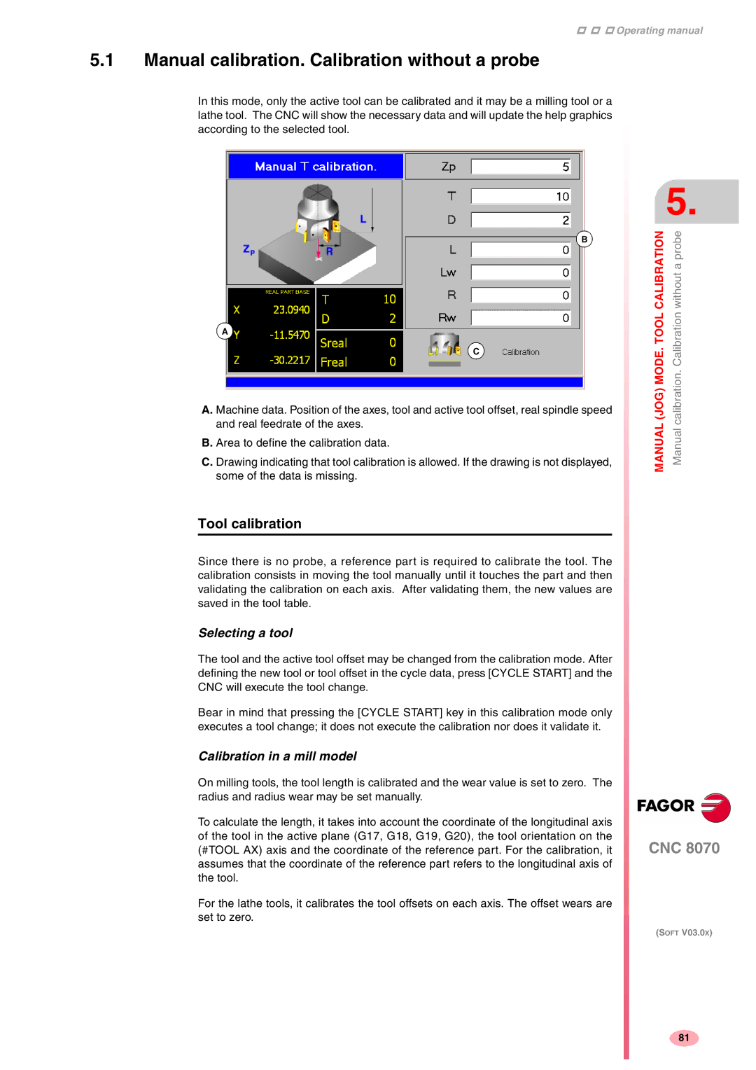
In this mode, only the active tool can be calibrated and it may be a milling tool or a lathe tool. The CNC will show the necessary data and will update the help graphics according to the selected tool.
B
A
C
A. Machine data. Position of the axes, tool and active tool offset, real spindle speed and real feedrate of the axes.
B. Area to define the calibration data.
C. Drawing indicating that tool calibration is allowed. If the drawing is not displayed, some of the data is missing.
Tool calibration
Since there is no probe, a reference part is required to calibrate the tool. The calibration consists in moving the tool manually until it touches the part and then validating the calibration on each axis. After validating them, the new values are saved in the tool table.
Selecting a tool
The tool and the active tool offset may be changed from the calibration mode. After defining the new tool or tool offset in the cycle data, press [CYCLE START] and the CNC will execute the tool change.
Bear in mind that pressing the [CYCLE START] key in this calibration mode only executes a tool change; it does not execute the calibration nor does it validate it.
Calibration in a mill model
On milling tools, the tool length is calibrated and the wear value is set to zero. The radius and radius wear may be set manually.
To calculate the length, it takes into account the coordinate of the longitudinal axis of the tool in the active plane (G17, G18, G19, G20), the tool orientation on the (#TOOL AX) axis and the coordinate of the reference part. For the calibration, it assumes that the coordinate of the reference part refers to the longitudinal axis of the tool.
For the lathe tools, it calibrates the tool offsets on each axis. The offset wears are set to zero.
5.
CALIBRATION | without a probe |
MANUAL (JOG) MODE. TOOL | Manual calibration. Calibration |
CNC 8070
(SOFT V03.0X)
81