Operating manual
9.
MAGAZINE TABLE | Tool table |
TOOL AND |
|
CNC 8070
(SOFT V03.0X)
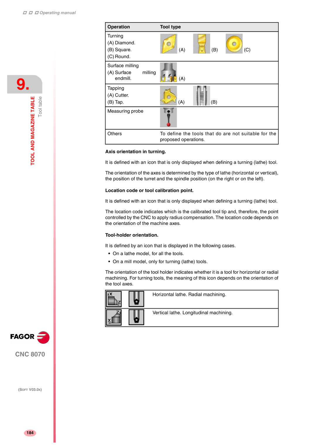
Operation | Tool type |
|
|
|
|
|
|
Turning |
|
|
|
(A) Diamond. |
|
|
|
(B) Square. | (A) | (B) | (C) |
(C) Round. |
|
|
|
|
|
|
|
Surface milling |
|
|
|
(A) Surface | milling |
|
|
endmill. | (A) |
|
|
|
|
|
|
Tapping |
|
|
|
(A) Cutter. |
|
|
|
(B) Tap. | (A) | (B) |
|
|
|
| |
Measuring probe |
|
| |
|
| ||
Others | To define the tools that do are not suitable for the | ||
| proposed operations. |
|
|
|
|
|
|
Axis orientation in turning.
It is defined with an icon that is only displayed when defining a turning (lathe) tool.
The orientation of the axes is determined by the type of lathe (horizontal or vertical), the position of the turret and the spindle position (on the right or on the left).
Location code or tool calibration point.
It is defined with an icon that is only displayed when defining a turning (lathe) tool.
The location code indicates which is the calibrated tool tip and, therefore, the point controlled by the CNC to apply radius compensation. The location code depends on the orientation of the machine axes.
Tool-holder orientation.
It is defined by an icon that is displayed in the following cases.
•On a lathe model, for all the tools.
•On a mill model, only for turning (lathe) tools.
The orientation of the tool holder indicates whether it is a tool for horizontal or radial machining. For turning tools, the meaning of this icon depends on the orientation of the tool axes.
Horizontal lathe. Radial machining.
Vertical lathe. Longitudinal machining.
184
