Operating manual
6.
Profile editor | |
EDITING |
|
6.9Profile editor
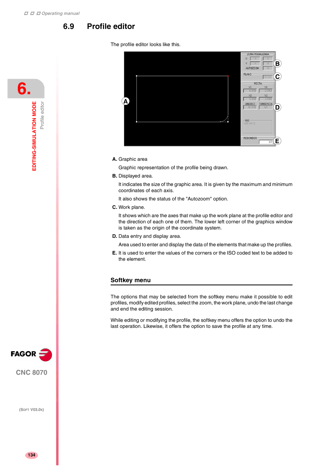
The profile editor looks like this.
B
C
A
D
E
A. Graphic area
Graphic representation of the profile being drawn.
B. Displayed area.
It indicates the size of the graphic area. It is given by the maximum and minimum coordinates of each axis.
It also shows the status of the "Autozoom" option.
C. Work plane.
It shows which are the axes that make up the work plane at the profile editor and the direction of each one of them. The lower left corner of the graphics window is taken as the origin of the coordinate system.
D. Data entry and display area.
Area used to enter and display the data of the elements that make up the profiles.
E. It is used to enter the values of the corners or the ISO coded text to be added to the element.
Softkey menu
The options that may be selected from the softkey menu make it possible to edit profiles, modify edited profiles, select the zoom, the work plane, undo the last change and end the editing session.
While editing or modifying the profile, the softkey menu offers the option to undo the last operation. Likewise, it offers the option to save the profile at any time.
CNC 8070
(SOFT V03.0X)
134