Operating manual
3.4Graphic screen
To display a graphic representation of the program that is running and take measurements on the graphics.
Description of the graphics window
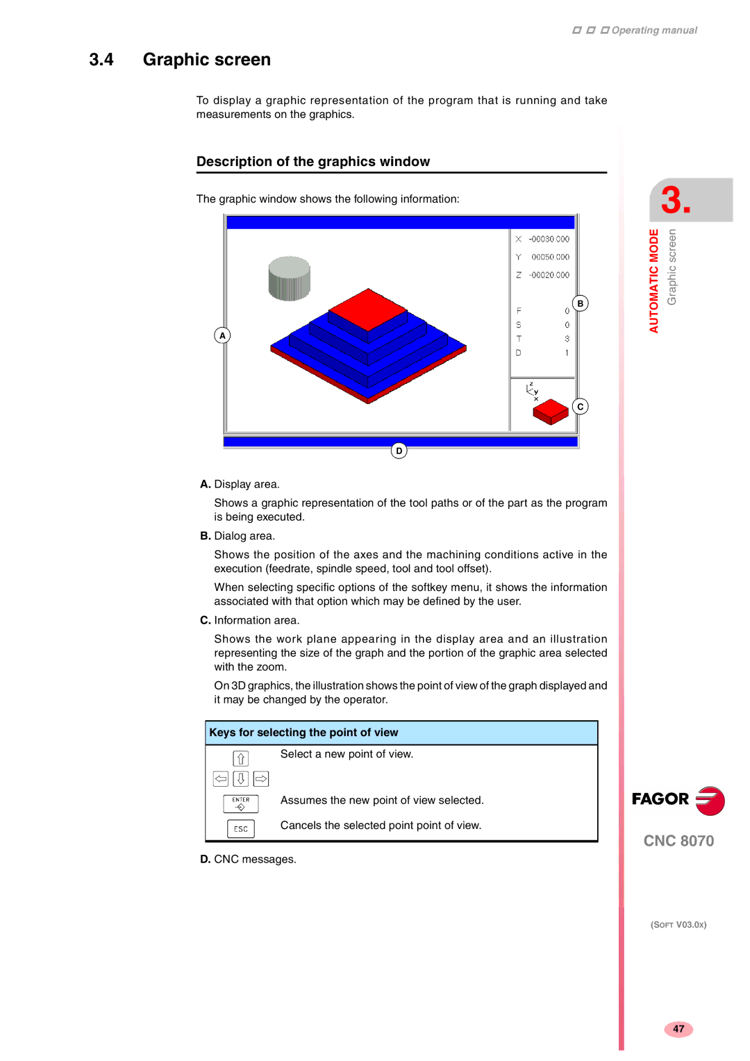
The graphic window shows the following information:
B
A
C
D
A. Display area.
Shows a graphic representation of the tool paths or of the part as the program is being executed.
B. Dialog area.
Shows the position of the axes and the machining conditions active in the execution (feedrate, spindle speed, tool and tool offset).
When selecting specific options of the softkey menu, it shows the information associated with that option which may be defined by the user.
C. Information area.
Shows the work plane appearing in the display area and an illustration representing the size of the graph and the portion of the graphic area selected with the zoom.
On 3D graphics, the illustration shows the point of view of the graph displayed and it may be changed by the operator.
Keys for selecting the point of view
Select a new point of view.
Assumes the new point of view selected.
Cancels the selected point point of view.
D. CNC messages.
3.
AUTOMATIC MODE | Graphic screen |
CNC 8070
(SOFT V03.0X)
47