Operating manual
5.3.2Lathe model ("plane" geometrical configuration)
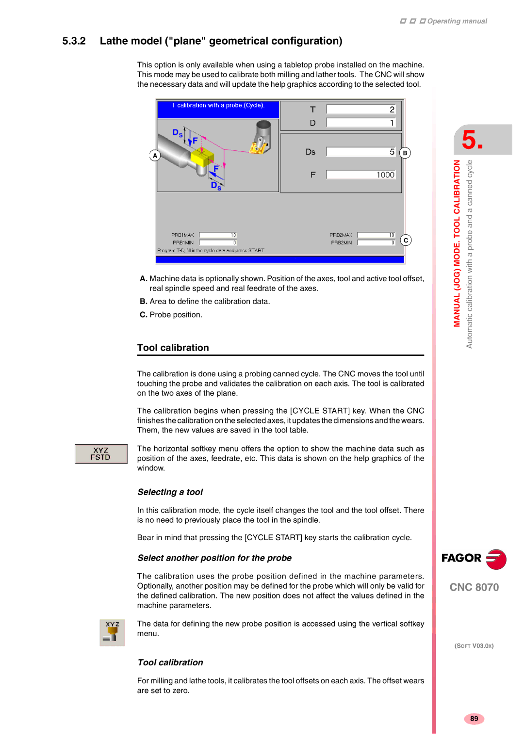
This option is only available when using a tabletop probe installed on the machine. This mode may be used to calibrate both milling and lather tools. The CNC will show the necessary data and will update the help graphics according to the selected tool.
AB
C
A.Machine data is optionally shown. Position of the axes, tool and active tool offset, real spindle speed and real feedrate of the axes.
B.Area to define the calibration data.
C.Probe position.
Tool calibration
The calibration is done using a probing canned cycle. The CNC moves the tool until touching the probe and validates the calibration on each axis. The tool is calibrated on the two axes of the plane.
The calibration begins when pressing the [CYCLE START] key. When the CNC finishes the calibration on the selected axes, it updates the dimensions and the wears. Them, the new values are saved in the tool table.
The horizontal softkey menu offers the option to show the machine data such as position of the axes, feedrate, etc. This data is shown on the help graphics of the window.
Selecting a tool
In this calibration mode, the cycle itself changes the tool and the tool offset. There is no need to previously place the tool in the spindle.
Bear in mind that pressing the [CYCLE START] key starts the calibration cycle.
Select another position for the probe
The calibration uses the probe position defined in the machine parameters. Optionally, another position may be defined for the probe which will only be valid for the defined calibration. The new position does not affect the values defined in the machine parameters.
The data for defining the new probe position is accessed using the vertical softkey menu.
Tool calibration
For milling and lathe tools, it calibrates the tool offsets on each axis. The offset wears are set to zero.
5.
CALIBRATION | a canned cycle |
MANUAL (JOG) MODE. TOOL | Automatic calibration with a probe and |
CNC 8070
(SOFT V03.0X)
89
