Controller Link Units
Controller Link Units
Page
Omron Product References
Omron
Unit Versions
Unit Version Notation on Products
Confirming Unit Versions with Support Software
Using the Unit Version Labels
Unit Version Notation
Function Support by Unit Version
Unit Versions and Manufacturing Dates/Lot Numbers
Viii
Table of Contents
Data Links 105
Appendices
Xii
Name Contents Cat. No Suffixes omitted
About this Manual
Xiv
Read and Understand this Manual
Application Considerations
Disclaimers
Xviii
Precautions
General Precautions
Safety Precautions
Intended Audience
Operating Environment Precautions
Operating Environment Precautions
Applications Precautions
Xxiii
Conformance to EC Directives
EMC Directives
Low Voltage Directive
Section
What Is the Controller Link?
Wired System
Overview
Section
Branch Wiring
Long-distance Wiring
Converting Part of the Transmission Line to Optical Fiber
Token Ring Mode
CS1W-CLK12-V1 CVM1-CLK12
Token Bus Mode
Connecting Repeater Units Using GI Optical Fiber Cable
Message Service
Automatic Setting
Manual Setting
Data Links
Error Log
Or the message service function
Status Area
Features
Features of Twisted-pair Cable
Features of Optical Fiber Cable
Specifications
Compatible with Different Node Configurations
Improved Error Handling
Flexible Inter-network Connections
Features and Functions of Version-1 Models
Total length of wired networks can be extended
Devices can be modularized
Up to 62 nodes can be connected
Specifications and Configurations
System Configuration
Branch Wiring
General Specifications
Maximum Configuration of 62 Nodes
Communications Specifications
Items Specifications
Within 1 segment See Entire network
PCF type GI type
Wired System
Controller Link Unit Models and PLCs
External Appearance Installation
Tables Weight
Max No.
Units per PLC
CS/CJ-series Controller Link Unit Models
Unit Ver .2 Pre-Ver .2 Without -V1 suffix Suffix
Name Model Current consumption Number Per Unit a Units
Repeater Units when Required
Devices for Connection
Communications Cables
Relay Terminal Blocks
Name Model Remarks
Programming Devices
Programming Device for the PLC
Programming External Model Applicable PLCs Device
Using an Independent Computer
Controller Link Support Software Version
Software External Model Applicable PLCs Remarks
EV2 HG/HE, CVM1
Controller Link Support Software Menu Overview
CX-Programmer
When Operating on Personal Computer as Peripheral Software
When Operating on Personal Computer Connected as a Node
Selection of Communications Functions
Software External Model Applicable PLCs
Basic Procedures
Preparations C200HX/HG/HE and CQM1H-series PLCs
CVM1, CV-series, and CS/CJ-series PLCs
Application Precautions
Communications error type Data link areas
C200HX/HG/HE PLC
Section
Section
Basic Procedures
Data Links Procedures
Manually Setting Data Links
Set the data link mode
Automatically Setting Data Links
Start the data links
CS/CJ Series Word 0 of DM30000 + 100 ⋅
AR 0700 operating level #0
CV-series PLCs Console Only
Gramming Console
Section
To 1 Type
CX-Programmer version 3.2 or higher
Chain Type
CS/CJ Series Word 0 of DM30000 + 100 ⋅ N
Message Service Procedure
Register routing tables if using inter-network connections
Contents Remarks
Create the I/O tables
Create the user program
Section
Installation and Wiring
Component Names and Functions
CS-series Controller Link Units
Wired Unit Indicators
Name Color Status Meaning
Dimensions Unit mm
CJ-series Controller Link Units
For details, refer to 9-1 Troubleshooting Using Indicators
Component Names and Functions
Node address switches Refer to p
3 C200HX/HG/HE Controller Link Unit
Yellow Lit Data reception Receive Not lit No data reception
Unit number switches Refer to p
4 CVM1 and CV-series Controller Link Unit
34.5
5 CQM1H-series Controller Link Unit
Wire-to-Wire Repeater Unit
Repeater Unit Indicators
Dimensions Unit mm
Wire-to-Optical H-PCF Repeater Unit
Wire-to-Optical GI Repeater Unit
Unit Installation
Installing One Controller Link Unit
Installing Two Controller Link Units
Mounting Controller Link Units
C200HX/HG/HE PLCs
Installing with Another Communications Unit
Installing with a PC Card Unit
CVM1 and CV-series PLCs
CS-series PLCs
Expansion CPU Rack
CPU Rack
CJ-series PLCs
Mum current of 4.6 a 5 V and maximum power of 30 W
Mounting a Repeater Unit
CQM1H-series PLCs
Screw-mounting a Repeater Unit
Mounting a Repeater Unit on DIN Track
DIN Track
Wiring
Communications Cables
Communications Cables
End Plate PFP-M 2 Plates required per Repeater Unit
Connecting the Shield Line
Terminal Block Connections
Not Unit a Relay Terminal Block
Connecting the Communications Cables
Using a Relay Terminal Block
Apply vinyl tape or a heat-shrinking tube
Do not pull on a communication cable
Power Supply Wiring
Mark Signal name Line color
Repeater Units
Power Supply Specifications
Laying Optical Cable CS1W-RPT02/03 Only
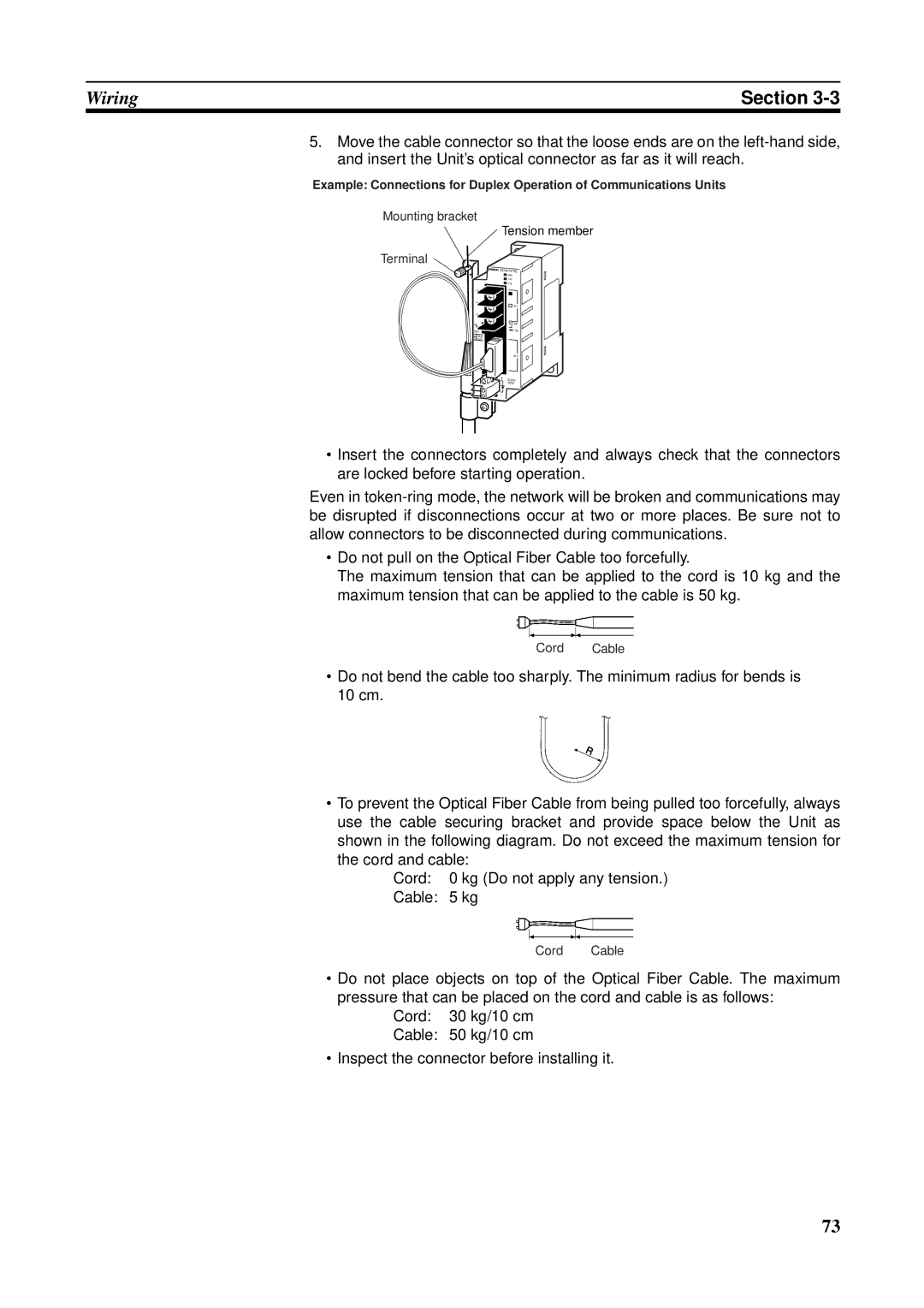
Mounting bracket Tension member Terminal
Name Specifications Model
Name Model Specifications
Optical Bus or Optical Ring System H-PCF Cable
Optical Fiber Cables Indoor Use Only
Optical Fiber Cables with Connectors Indoor Use Only
Optical Fiber Cable Accessories
Specifications Length Model
Name Model Specifications Manufacturer
CS1W-RPT03 GI
Optical Fiber Cables
50/125 ∝m AGF Cable
Minimum Standard Maximum Unit Conditions
Connectors
Constructing Networks with Repeater Units
62.5/125 ∝m AGF Cable
Specifications within Remarks Each segment
Segments
Branch Wiring 2-stage Repeater Unit Connection
Number of Repeater Units
Examples of Correct Repeater Unit Connections
Long-distance Wiring 2-stage Repeater Unit Connection
Examples of Incorrect Repeater Unit Connections
Partial Optical Conversion 2-stage Repeater Unit Connection
More than 2 Stages of Repeater Units
Branch Wiring
Long-distance Wiring
Terminating Resistance
Partial Conversion to Optical Fiber
Section
Preparations for Communications
CS-series Controller Link Units
Overview
Unit Number
Node Addresses
Pins Baud rate Maximum Transmission distance
Baud Rates
Default setting is 2 Mbps, 500 m
Bottom switch Terminating resistance
CJ-series Controller Link Units
Setting range Nodes To F default is
Setting range Nodes 01 to 32 default is
Node
Baud Rates
C200HX/HG/HE Controller Link Units
C200HX/HG/HE PLC
Baud Rate and Operating Level
Always leave pin 3 OFF
Operating Level
Baud Rate Pins 1
Setting the Operating
Baud Rates and Operating Levels
Level Pin
Pin Operating level Node
Setting Baud Rates
Always keep pins 3 and 4 set to OFF
CVM1 and CV-series Controller Link Units
Node Addresses
Unit
Set the following pins for the baud rate setting DIP switch
Switch Baud rate Maximum Transmission distance Pin
Switch at the front Terminating resistance
Setting Baud Rate
Switch Terminating Nodes Resistance
CQM1H-series Controller Link Units
Pin Sion dis Tance
101
Repeater Units
Wire-to-Wire Repeater Unit
Wire-to Repeater
Terminating Resistance Switch for SL1
Terminating Resistance Switch for SL2
Switch Terminating resistance
Data Links
Manually Setting Data Links
What Are Data Links?
CS/CJ-series Controller Link Unit Functions by Unit Version
Easy Setting
Offsets
Automatically Setting Data Links with Equality Layout
Automatic Setting Data Links with 1N Allocations
Type Model
Using Offsets
Offsetting Image
Data Link Specifications
Communications error type Data link area
Description
Differences between Manual and Automatic Setting
Manual setting Automatic setting
Setting Data Links
Selecting Manual or Automatic Setting
Manual Setting
Transferring from a Programming Device
Data Link Table Specifications
Setting item Setting range
Transferring from a Computer Node
CS/CJ-series PLCs
116
C200HX/HG/HE PLCs
118
CVM1 and CV-series PLCs
Used. Refer to 5-4 Checking Data Link Status for details
CQM1H-series PLCs
121
Precautions
Data link start word 1 + Total number of send/receive
Words in area ≤ 247 IR Area
W307 for information on the Controller Link Support Board
Manual Setting Examples
Device Information Settings
SAMPLE1.CLK Same Allocation to All Nodes
Data Link Area Structure
124
Device Information Setting
SAMPLE2.CLK Different Allocations to Each Node
SAMPLE3.CLK Creating Data Link Groups within a Network
Device Information Setting Data Link Tables
SAMPLE4.CLK Receiving Only Part of Send Data and Offsets
Only area 2 is used in this example
Automatic Setting
Automatic Setting, Equality Layout
CS/CJ-series Startup Node
Automatic Setting, 1N
Allocations
Between master and slave nodes
Setting Range for Automatic Setting
Equality Layout
133
Features of Common Type 1N Allocation
1N Allocation, Common Type
135
136
137
Features of 1 to 1 Type 1N Allocation
1N Allocations, 1 to 1 Type
139
140
Features of Chain Type 1N Allocation
1N Allocation, Chain Type
142
143
144
Settings
C200HX/HG/HE Startup Node
146
CVM1 or CV-series Startup Node
148
149
CQM1H-series Startup Node
Automatic Setting Example
Settings for Equality Layout
Link areas that are created as a result
DM Parameter Area
DM Parameter Setting Example for 1N Allocation, Common Type
Data Link Areas Created
Starting and Stopping Data Links
Data Link Areas
Manually Set Data Links
Automatically Set Data Links
Using a Programming Device or the User Program
CS/CJ-series Start Bit
C200HX/HG/HE Start Bit
Using Fins Commands
LED Indicators
Check the Link and M/A indicators on the front of the unit
Name Color Status Contents
Checking Data Link Status
157
Following shows an example of a remaining receive area
Name Function
Data Link Status Storage Format CS/CJ Series Only
Data link status storage area is set as follows
Only status for nodes 1 to 6 are saved
Matic settings
Specification
Checking by Manipulating Bit/Word Status
Error Detection Program Example
Programming Examples for Processing Data when Errors Occur
Processing Data Only when Data Links Are Operating Normally
Writing 0000 in the Data Link Area when Errors Occur
Data Link Example Communications Error at Node
164
Message Service
Introduction
Send and Recv
CS/CJ-series PLCs
168
C200HX/HG/HE PLCs
@SEND90
170
171
Timer/counters numbers 0 to 2047 can send and receive data
CIO
Section CVM1 and CV-series PLCs
Word for data reception at the destination node, N
174
CQM1H-series PLCs
176
177
178
179
180
181
Beginning word for storing response data
Cmnd
Example Commands for CVM1, CV-series and CS/CJ-series PLCs
Type of command Code
Send/Receive Data Areas
Area Range
Area Range CV500, CVM1-CPU01
CVM1-CPU11/21
Selecting Communications Instructions
Com
Tents
Puter Or CV
Read/write
Message Service Specifications
Using the Message Service
Name Address Contents Word Bit
SEND/RECV Flags
Name Operating Address Contents Level
Name Address Contents
Network Status
CVM1, and CV-series PLCs
Word Bits Contents
SEND/RECV Flag Operations
Communications Instruction Response Codes
Example
C200HX/HG/HE
CQM1H-series PLC
Response Codes
CS/CJ-series, CVM1,
Simultaneous Execution of Communications Instructions
C200HX/HG/HE PLCs CS/CJ-series, CVM1, and CV-series PLCs
PLC Programming Examples
On the next
195
196
197
198
Fins Commands and Responses
Fins Communications Service
Sending and Receiving Fins Commands and Responses
Applicable Units for Fins Commands
Command Codes
Any parameters must follow the command code
Execution result
Commands and Responses for Controller Link Units
Command Codes
Command Block
Response Block
Response Block For C200HX/HG/HE, CVM1, and CV-series PLCs
For CS/CJ-series and CQM1H-series PLCs
Parameters
Model
Wired/Optical response
Reads the Controller Link Unit’s controller status
Unit. Always set to 00 Hex
204
Network Status Read
Corresponding to the node address
0 0 0 0
Default value 32 nodes
Reads the data link operational status
Ified as a 2-byte 4-digit hexadecimal number as follows
Hex 32 nodes
208
Data that was sent by the command
One was sent is returned
Reads the PLC’s error log
Broadcasts test data to all nodes in a specified network
Hexadecimal decimal 0 to
Response gives the number of records actually read
Error LOG Clear
Configuration of each error record is as follows
Command PLC mode Name Code
Memory Area Designations
Specified for CQM1H-series PLCs
Word/Bit Addresses
Each word/bit address specifies a specific bit or word
Memory Area Code
Data Configuration
Word Contents or PV Two Bytes
Parameters Memory area code command The data area to read
Flag or Bit Status One Byte
Parameters Memory area code command The data area to write
Memory Areas
Memory area Data No. Code Bytes
Sequence starting from the beginning address
Memory area designations
Program Area Write
Data command The data to be written
02 Hex Monitor mode 04 Hex RUN mode
8 RUN
Stop
Area data response As follows
Meaning Unit Hex
Command Block Response Block
Reads the status of the Controller
0 0
Clock Read
Value Day
Parameters Error reset code command Set to Ffff Hex
Parameters Range
Value Function
Memory area Data
Response
Designations for memory area designations
Area Data type Memory area Number Code Bytes
Configuration
Response Codes
IR, SR, LR, HR, and AR Areas
Network Relay Errors
Relay Errors
Response Codes and Troubleshooting
To some cause such as a routing table error
CPU Unit
Exist
228
229
230
231
232
Network Interconnections
What is Network Interconnection?
Interconnecting Controller Link Networks
Interconnecting Different Types of Networks
235
Remote Programming and Monitoring
Local Networks
Sysmac Support Software and CV Support Software
Remote Controller Link Networks
Sysmac Support Software or CV Support Software
Other Remote Networks
CX-Programmer Programming Device
Routing Tables
Creating Routing Tables
Appropriate Unit according to the routing tables
Local Network Table
Setting Routing Tables
Created
Relay Network Table
Network end network not directly connected to the local PLC
Routing Table Setting Procedure
Editing Local Network Tables
Local network
Editing Relay Network Tables
Saving Routing Tables
Connecting to the PLC
Routing Table Enable Bit C200HX/HG/HE and CQM1H-series Only
Transferring Routing Tables
Operating level 0 DM Operating level 1 DM
Example Routing Table Settings
PCs
Nodes
Routing Tables on PLC
246
Communications Timing
Communications Mechanism
Data Transmissions over the Network
Setting the Polling and Polled Nodes
Network Parameters
No. of Polled Nodes per Communications Cycle
Network parameter Setting Default Range Value
Communications Cycle Time
Specifying Network Parameters
Active Data Links
Instruction When sent When received
Inactive Data Links
Calculation Example
Communications conditions are as follows
Being issued
Data Link I/O Response Time
Data Exchange Timing
Bytes
Synchronous Mode
Data Processing Time
Under Asynchronous
CS/CJ-series PLCs, CVM1
Calculation Example
Time Case
257
258
259
260
261
Minimum Response Time
CVM1 and CV-series PLCs Under Asynchronous Operation
Maximum Response Time
264
Message Delay Times
1 CS/CJ-series, CVM1, and CV-series PLCs
Data Processing Time see
Data Transmission Time
Link Service Processing Source and Destination Nodes
Transmission Delay Time
Link Servicing Interval Source and Destination Nodes
Transmission Processing
That transmits event frames before the Send command is sent
Maximum Delay Time
Reception Processing
Number of words transferred ⋅ 0.00075 + 1.3 ms
268
269
2 C200HX/HG/HE and CQM1H-series PLCs
SEND90
Responses Number of words transferred ⋅ 0.00125 ms + 3 ms
Responses Number of words transferred ⋅ 0.00125 ms + 2.3 ms
RECV98 Instruction
272
273
274
Troubleshooting and Maintenance
Troubleshooting Using Indicators
Troubleshooting with RUN, ERC, ERH and INS Indicators
1 CS/CJ-series Controller Link Units
CS-series Unit
277
278
Troubleshooting with LNK and M/A Indicators
Using the following table
Data Link Cannot be
Started
Troubleshooting of Other Errors
Node Cannot Participate
Data Link
Stopped
Configuring a Network with 33 Nodes or More
Problem Status Cause and remedy
282
Configuring a Network with 32 Nodes or Less
2 C200HX/HG/HE and CQM1H-series Controller Link Units
284
285
286
CVM1 and CV-series Controller Link Units
288
289
290
291
Status Area and Troubleshooting
Troubleshooting with the PWR Indicator
Troubleshooting with the T/R1 and T/R2 Indicators
Error Information CIO 1500 + 25 x Unit No
Status Area
294
Bit Status and Error Processing
Data Link Status
Bit status Probable cause Probable remedy
296
Refer to 7-4 Setting Rout
Other Status
Terminating Resistance Status CIO 1500 + 25 ⋅ Unit No. +
Stopping Data Links
Duplicate Operating Levels/Refresh Error AR
Routing Table Error/Unit Restart Bits AR
Service Time AR 16, AR
2 C200HX/HG/HE Controller Link Units
Polling Node Address, Startup Node Address SR 238, SR
Data Link Status SR 239 to SR 241, SR 243 to SR
Operating Level Status SR
Troubleshooting with Status Flags
Data Link Status First Data Link Status Word + 0 to +
302
303
Error Information CIO 1500 + 25 ⋅ Unit No
3 CVM1 and CV-series Controller Link Units
Data Link Status CIO 1500 + 25 ⋅ Unit No. + 7 to +
306
307
Error Information IR
4 CQM1H-series Controller Link Units
Polling Node Address, Startup Node Address IR
Network Participation Status IR 192 and IR
Local Data Link Participation Status IR
Data Link Status IR 91 to IR
310
311
Routing Tabless and reset
Terminating Resistance Status IR
Error Log
Error Log Table
Error Log Table Configuration
Error Codes
Tents of the errors
Time Information
1st byte 2nd byte
315
Command block
Response block
317
318
319
Reading and Clearing Error Logs
Error Status
Reading an Error Log
Clearing an Error Log
Example Display of Error List
Error message Troubleshooting
322
Cleaning and Inspection
Cleaning
Inspection
Tools and Equipment Need for Inspection
Handling Precautions
Replacing the Unit
Bit address Unit
Word Unit
Setting the Unit after Replacement
Resetting Network Parameters
326
Using the Controller Link Support Software
Not Using the Controller Link Support software
C200HX/HG/HE and CQM1H-series Controller Link Units
3.. . Turn off all nodes in the Controller Link Network
CS/CJ-series, CVM1, and CV-series Controller Link Units
329
330
Adding Nodes and Editing Active Data Link Tables
Adding Nodes Using a Repeater Unit
Example of Adding Nodes Using a T-branch Line
Example of Adding Nodes with a Repeater Unit on One End
Procedure for Adding Nodes
Precautions when Connecting Nodes Using a Repeater Unit
System Configuration after Adding Nodes
Adding Nodes with a Repeater Unit at One End
Systems Wired with an Existing Repeater Unit
Systems with an Existing T-branch Line
Operations when Changing Data Link Tables
Changing the Data Link Tables with Active Data Links
Example of Changing Data Link Table with Active Data Links
Model Remarks
337
Procedure
339
340
341
342
Standard Models Controller Link Units
Controller Link Support Board
Controller Link Support Software
Communications Cables Twisted-pair Cables
CX-Programmer with CX-Net
CPU Units and Programming Devices
CPU Units
Applicable Name Model number Applicable PLCs Computer
Other Products Used with Controller Link Units
Page
Memory Areas
CS/CJ-series PLCs
Auxiliary Area
CS/CJ CPU Bus Unit Duplication Error Flag
CS/CJ CPU Bus Unit Error, Unit Number Flags
Error Information CIO 1500 + 25 ⋅ Unit No. See
CIO Area CS/CJ CPU Bus Unit Area
349
350
DM Area CS/CJ CPU Bus Unit Area
Memory AreasAppendix B
Common Type
To 1 Type
Chain Type
C200HX/HG/HE PLCs
SR Area
Communications Instruction Response Codes SR 237 See
Duplicate Operating Levels/Refresh Error AR 00 See
Routing Table Error/Unit Restart Bits AR 01 See
AR Area
Operating Level Status SR 252 See pages 189
Service Time AR 16, AR 17 See
DM Parameter Area
CVM1 and CV-series PLCs
CIO Area CPU Bus Unit Area
CPU Bus Unit Numbers
359
DM Area CPU Bus Unit Area
Word Bits Name Contents
CQM1H-series PLCs
Data Link Start Bit AR 07 See
Local Data Link Participation Status IR 90 See
Data Link Status IR 91 to IR 93 See pages 156
Terminating Resistance Status IR 95 See
PLC Setup Settings in DM Area
Controller Link Status Information
Automatic Data Link Parameters DM 6401 to DM 6409 See
Using the Relay Terminal Block
Appearance Name Model number Remarks
Replacing a Controller Link Unit with a Relay Terminal Block
367
Page
Numerics
Index
371
372
373
374
Revision code Date Revised content
Revision History
Revision History
Pages 115, 117, 119, and 120 PC changed to PLC
Omron Corporation Control Devices Division H.Q
Regional Headquarters
Authorized Distributor