RëÉêÛë=dìáÇÉ
BåÅçêÉ=mêÉëÉåí~íáçå=póëíÉã
Encore Presentation System User’s Guide Rev
BåÅçêÉ=mêÉëÉåí~íáçå=póëíÉã=√=rëÉêÛë=dìáÇÉ
Technical Support
`çãé~åó=ÇÇêÉëë
Barco, Inc
Barco N.V
Aç=kçí=oÉãçîÉ=`çîÉêë=çê=m~åÉäë
LéÉê~íçêë=p~ÑÉíó=pìãã~êó
Tokfkd
QÉêãë=få=qÜáë=j~åì~ä=~åÇ=bèìáéãÉåí=j~êâáåÖ=
ECP #
`Ü~åÖÉ=eáëíçêó
~ÄäÉ=çÑ=`çåíÉåíë
Table of Contents
Table of Contents
Table of Contents
Table of Contents
`Ü~éíÉê=T
Table of Contents
Table of Contents
ÉéÉåÇáñ=a=
Table of Contents
NK==fåíêçÇìÅíáçå
`Ü~éíÉê=píêìÅíìêÉ
PçÑíï~êÉ=sÉêëáçå
DÉåÉê~ä=fåëíêìÅíáçåë
Eçï=íç=rëÉ=qÜáë=dìáÇÉ
~îáÖ~íáåÖ
~ÄäÉ=çÑ=`çåíÉåíë=~åÇ=fåÇÉñ
QÉêãë=~åÇ=aÉÑáåáíáçåë
`çåîÉåíáçåë=
Operator refers to the person who uses the system
Çî~åÅÉÇ=sáÇÉç=mêçÅÉëëáåÖ
PóëíÉã=lîÉêîáÉï
BåÅçêÉ=cÉ~íìêÉë
Fåéìí=cäÉñáÄáäáíó
QÜÉ=båÅçêÉ=sáÇÉç=mêçÅÉëëçê
Lìíéìí=cäÉñáÄáäáíó
PÅ~äáåÖ=~åÇ=hÉóáåÖ
=tçêÇ=Äçìí=i~óÉêë
Wilderness
DSK
=tçêÇ=Äçìí=aÉëíáå~íáçåë
PáåÖäÉ=jáñÉê=bÑÑÉÅíë
BÑÑÉÅí=`çãÄáå~íáçåë
Single Mixer Effect
PIP1A Key 1B
Dual Mixer Effect
Aì~ä=jáñÉê=bÑÑÉÅíë
Triple Mixer Effect
QêáéäÉ=jáñÉê=bÑÑÉÅíë
BîÉåí=j~å~ÖÉãÉåí
FåíÉÖê~íáçå=ïáíÜ=páÖå~ä=oçìíÉêë
BåÅçêÉ=`çåÑáÖìê~íçê
`çåÑáÖìê~íáçå=ééäáÅ~íáçåë
~êÅç=~Åâìé=~åÇ=oÉëíçêÉ=ríáäáíó=
MêçÇìÅí=aáÑÑÉêÉåíá~íáçå
Feature Small Controller SC Large Controller LC
PçÑíï~êÉ=sÉêëáçå=NKOQ=cÉ~íìêÉë
Stacked Configuration Support
Feature Enhancements
KÉï=cÉ~íìêÉ=oÉîáÉï
PçÑíï~êÉ=sÉêëáçå=NKOO=cÉ~íìêÉë
Enhanced Events Manager Support
Presets Fully Active
Stacked Configuration Frame Grab
Enhanced Source Preview
PçÑíï~êÉ=sÉêëáçå=NKNV=cÉ~íìêÉë
Third Party Router Support
Wide Screen Link Diagnostics
Color Keying using the Color Picker
External Trigger Function
User Keys
Layer Join Mode
Support for Analog Backgrounds
Support for Two Separate Matte Colors
Flicker Reduction for Interlaced Formats
Programmable Controller Lockout
Destination Based Effects Menu
Programmable Raster Box Size
NK==fåíêçÇìÅíáçå
Få=qÜáë=`Ü~éíÉê
OK==e~êÇï~êÉ=lêáÉåí~íáçå
Air Intake Ports
SáÇÉç=mêçÅÉëëçêë
SáÇÉç=mêçÅÉëëçê=cêçåí=m~åÉä
Chassis Handles
SáÇÉç=mêçÅÉëëçê=oÉ~ê=m~åÉä
Smñ=cêçåí=m~åÉä
Program 2 Out DVI
Preview Out DVI
Preview Out Analog
Program 2 Out Analog
Genlock
12 M/E 1 Connectors 13 M/E 2 Connectors 14 M/E 3 Connectors
AC Connector
Ethernet Port
Figure below illustrates the VPx rear panel
Smñ=oÉ~ê=m~åÉä
Program 2 Out Analog
=tçêÇ=Äçìí=jLb=`çååÉÅíçê=mêáçêáíó
11 M/E 1 Connectors 12 M/E 2 Connectors 13 M/E 3 Connectors
Hardware Orientation
DVI Input a
JLb=`çååÉÅíçêë=EsmF
Analog Input a
HD/SDI Input a
Analog Input B
Source Link
DVI Input B
HD/SDI Input B
JLb=`çååÉÅíçêë=EsmñF
M/E Connectors, VPx
Source Link Out
JLb=fåéìí=kçíÉë
~äçÖ=fåéìí=cäÉñáÄáäáíó
MêçÖê~ã=lìíéìí=kçíÉë
YUV RGB
Keyboard Port
`çåíêçääÉê=oÉ~ê=m~åÉäë
USB B Port
Ext Comm
Tally Connector
AC Power
MultiMedia Card Slot
Hardware Orientation
PK==e~êÇï~êÉ=fåëí~ää~íáçå
~ÅâJjçìåí=fåëí~ää~íáçå
~ÑÉíó=mêÉÅ~ìíáçåë=
Råé~ÅâáåÖ=~åÇ=fåëéÉÅíáçå=
PáíÉ=mêÉé~ê~íáçå=
Table below provides cable and adapter information
`~ÄäÉ=~åÇ=Ç~éíÉê=fåÑçêã~íáçå
Fåëí~ää~íáçå
PáåÖäÉ=pÅêÉÉå=`çåÑáÖìê~íáçå
For this configuration, you will need
A Connections
Output Connections
QêáéäÉ=pÅêÉÉå=`çåÑáÖìê~íáçå
Block Diagram, Triple Screen Encore Configuration
A Connections
Output Connections
Hardware Installation
TáÇÉ=pÅêÉÉå=`çåÑáÖìê~íáçå
For this procedure, you will need
TDB
Connect the computer’s head 3 to processor 3, input 1A
, see the ScreenPRO-II Destination Setup section for details
TáÇÉ=pÅêÉÉå=`çåÑáÖìê~íáçå=mäìë=táÇÉ=pÅêÉÉå=mêÉîáÉï
Wide Screen Program/Preview Monitor PIPs
`çãéäÉíáåÖ=táÇÉ=pÅêÉÉå=mêÉîáÉï=pÉíìé
Hardware Installation
Single Screen Stack with 12 PIPs
PáåÖäÉ=pÅêÉÉå=pí~Åâ=`çåÑáÖìê~íáçå
Installation For this procedure, you will need
Stack Interconnections
Installation
Stack
TáÇÉ=pÅêÉÉå=pí~Åâ=`çåÑáÖìê~íáçå
TBD
Stack Interconnections a. On the first stack
A Connections
System ID Using the Unit ID Selector
`çååÉÅíáçå=lîÉêîáÉï
`çååÉÅíáçå=`Ü~êíë=
`Ü~êí=fåëíêìÅíáçåë
Router I/O Charts
Direct Encore Input Chart
Encore Destination Chart
DVI
~ãéäÉ=`çååÉÅíáçå=`Ü~êíë
OçìíÉê=fLl=`Ü~êíë=
~åâ=`çååÉÅíáçå=`Ü~êíë=
Router #2 Router Type Analog Digital
Router #4 Router Type Analog Digital
Router #6 Router Type Analog Digital
AáêÉÅí=båÅçêÉ=fåéìí=`Ü~êí=
BåÅçêÉ=aÉëíáå~íáçå=`Ü~êí=
Use of a Single High Definition Image
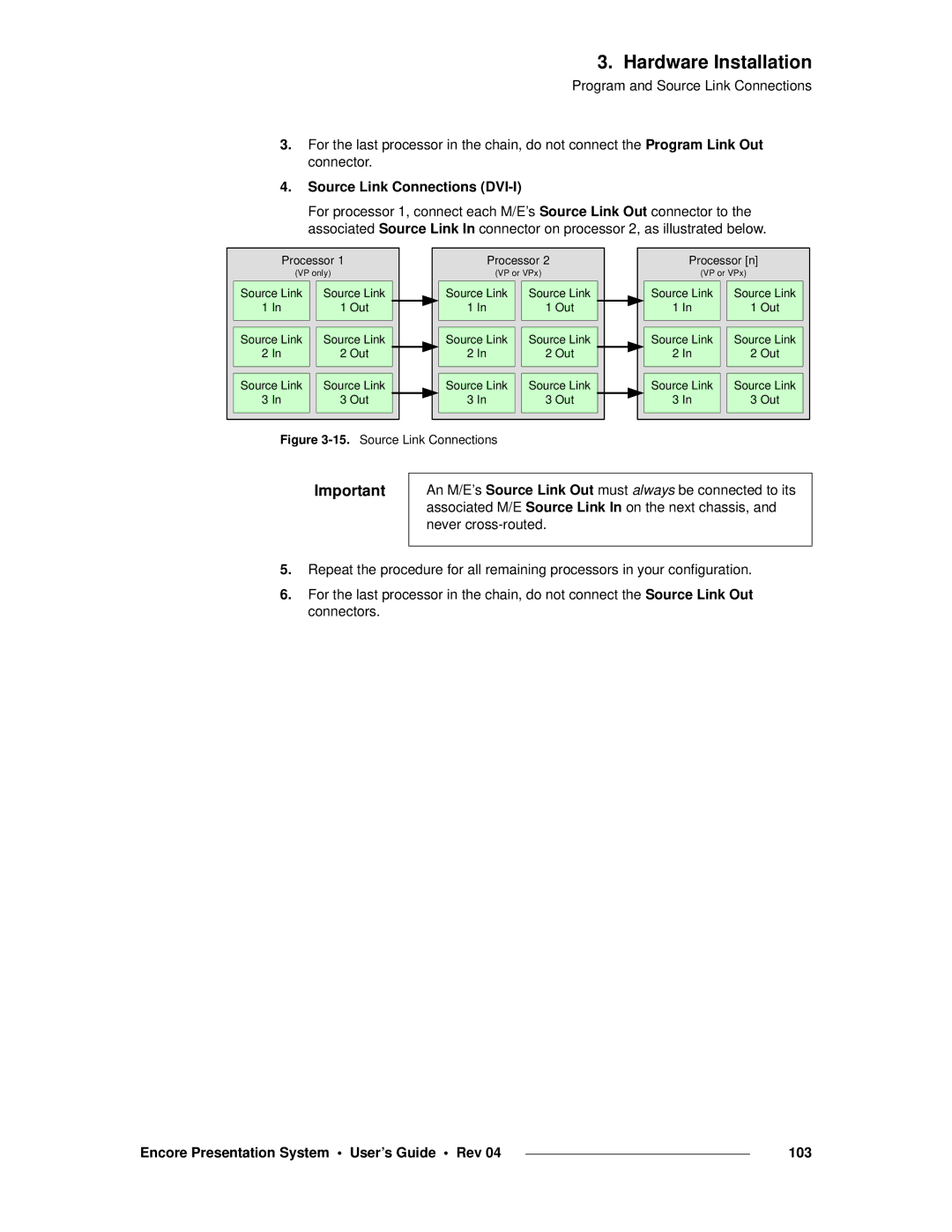
MêçÖê~ã=~åÇ=pçìêÅÉ=iáåâ=`çååÉÅíáçåë
LîÉêîáÉï=çÑ=bÇÖÉJäÉåÇáåÖ=qÉÅÜåçäçÖó
`çåíÉåí=`êÉ~íáçå=
10.HD Source Material Formatting
Use Of Multi-Head Graphics Boards
Image Overlap
SáÇÉç=mêçÅÉëëáåÖ
Edge Feathering
MêçàÉÅíçê=pÉíìé=~åÇ=póëíÉã=ÇàìëíãÉåíë
Encore Presentation System User’s Guide Rev 101
IÉÑí=gìëíáÑáÉÇ=`çåÑáÖìê~íáçå
`çååÉÅíáåÖ=mêçÖê~ã=~åÇ=pçìêÅÉ=iáåâë
Program Link Connections DVI-I
Encore Presentation System User’s Guide Rev 103
Source Link Connections DVI-I
16.Center Justification
`ÉåíÉê=gìëíáÑáÉÇ=`çåÑáÖìê~íáçå
19.Program Link Connections, Four Projectors
Encore Presentation System User’s Guide Rev 105
106
Encore Presentation System User’s Guide Rev 107
QK==`çåíêçääÉê=lêáÉåí~íáçå
Touch Screen Section
`çåíêçääÉê=i`=cêçåí=m~åÉä
System Keypad
Machine Control Section
Preset Section
Live Switch Section
Joystick Section
Layer/Aux Control Section
Program Preset Section
Transition Section
Group Control Section
Encore Presentation System User’s Guide Rev 111
`çåíêçääÉê=p`=cêçåí=m~åÉä
112
Crop
RëÉ=çÑ=`çäçê
Encore Presentation System User’s Guide Rev 113
`çåíêçääÉê=pÉÅíáçåë
Encore Presentation System User’s Guide Rev 115
QçìÅÜ=pÅêÉÉå=pÉÅíáçå
Softkeys
Rotary Knobs
Touch Screen
Encore Presentation System User’s Guide Rev 117
PóëíÉã=hÉóé~Ç
Seqs
Cancel
Encore Presentation System User’s Guide Rev 119
ÄéÜ~åìãÉêáÅ=hÉóé~Ç
Joystick Section
GçóëíáÅâ=pÉÅíáçå
Top
Reset
Adjust
Source
`çåëçäÉ=iáÖÜíáåÖ
~ÅÜáåÉ=`çåíêçä=pÉÅíáçå
MêÉëÉí=pÉÅíáçå
Preset Recall Options Menu . This menu accessed by
Encore Presentation System User’s Guide Rev 123
Delete
Next
Clear
AÉëíáå~íáçå=ìë
Encore Presentation System User’s Guide Rev 125
13.Source Selection Bus, Controller SC
PçìêÅÉ=pÉäÉÅíáçå=ìë
Encore Presentation System User’s Guide Rev 127
15.Layer Control Section, Controller SC
~óÉê=`çåíêçä=pÉÅíáçå
Encore Presentation System User’s Guide Rev 129
DSK
Encore Presentation System User’s Guide Rev 131
~óÉê=cìåÅíáçåë=pÉÅíáçå
Key
Border
Copy
Setup
Move Setup
Clone
Freeze
Preview OSD
Layer
All
IáîÉ=pïáíÅÜ=pÉÅíáçå
Live Switch
Encore Presentation System User’s Guide Rev 135
Qê~åëáíáçå=pÉÅíáçå
Auto
Trans
Go / +
Encore Presentation System User’s Guide Rev 137
Dêçìé=`çåíêçä=pÉÅíáçå
138
Encore Presentation System User’s Guide Rev 139
Program Preset Buttons
Presets to Program
MêçÖê~ã=mêÉëÉí=pÉÅíáçå
BG button in the Layer/Aux Control Section is not
~óÉêLìñ=`çåíêçä=pÉÅíáçå
Layer Buttons
ALL button in the Layer/Aux Control Section is not
AUX button in the Layer/Aux Control Section is not
Encore Presentation System User’s Guide Rev 141
Mix
Qê~åëáíáçå=cìåÅíáçåë=pÉÅíáçå
Effect
Encore Presentation System User’s Guide Rev 143
Shuffle
29.User Key Section, Controller LC
RëÉê=hÉó=pÉÅíáçå
Encore Presentation System User’s Guide Rev 145
RK==jÉåì=lêáÉåí~íáçå
DäçÄ~ä=oìäÉë
`çåîÉåíáçåë=áå=íÜáë=`Ü~éíÉê
Encore Controller
EçãÉ=jÉåì
Fåéìí=jÉåì=qêÉÉ
Fåéìí=jÉåì
Smpte
Fåéìí=jÉåì=aÉëÅêáéíáçå
Encore Presentation System User’s Guide Rev 149
Input Menu SRC1
~ HD SDI ~ SDI
Fåéìí=jÉåì=cìåÅíáçåë
Encore Presentation System User’s Guide Rev 151
~ Adjustment range 1.0 to
152
Encore Presentation System User’s Guide Rev 153
Input Configuration SRC1
Fåéìí=pìÄ=jÉåìë
Fåéìí=`çåÑáÖìê~íáçå=jÉåì
Aspect Ratio SRC1
ËéÉÅí=o~íáç=jÉåì
Encore Presentation System User’s Guide Rev 155
PáòáåÖ=jÉåì
Oversample Sizing SRC1
Figure below illustrates the Oversample Sizing Menu
Encore Presentation System User’s Guide Rev 157
`çäçê=~ä~åÅÉ=jÉåì
RGB Color Balance SRC1
Lìíéìí=jÉåì=qêÉÉ
Lìíéìí=jÉåì
Encore Presentation System User’s Guide Rev 159
Lìíéìí=jÉåì=aÉëÅêáéíáçå
Output Menu
Lìíéìí=pìÄ=jÉåìë
Lìíéìí=jÉåì=cìåÅíáçåë
Enhanced Output Menu
BåÜ~åÅÉÇ=lìíéìí=jÉåì
SOG / Y
Enhanced Output Settings Menu
Enhanced Output Test Pattern Menu
Encore Presentation System User’s Guide Rev 163
Genlock
DÉåäçÅâ=jÉåì
PÉííáåÖë=jÉåì
Settings
Encore Presentation System User’s Guide Rev 165
Test Pattern
QÉëí=m~ííÉêå=jÉåì
Encore Presentation System User’s Guide Rev 167
TáÇÉ=pÅêÉÉå=pÉííáåÖë=jÉåì
Total Projectors
Wide Screen Settings
Total Projectors 2W x 2H
Encore Presentation System User’s Guide Rev 169
# screens * vertical output resolution V overlap * # screens
Encore Presentation System User’s Guide Rev 171
Feather Setup
PóëíÉã=jÉåì=qêÉÉ
PóëíÉã=jÉåì
Encore Presentation System User’s Guide Rev 173
PóëíÉã=jÉåì=aÉëÅêáéíáçå
System Menu
PóëíÉã=pìÄ=jÉåìë
Soft
System Reset
PóëíÉã=oÉëÉí=jÉåì
Encore Presentation System User’s Guide Rev 175
Software Version
PçÑíï~êÉ=sÉêëáçå=jÉåì
Aá~ÖåçëíáÅë=pÉíìé=jÉåì
Diagnostics Setup
Encore Presentation System User’s Guide Rev 177
27.Widescreen Link Diagnostics Menu sample
Widescreen Link Diagnostics
28.Rotary Encoder Menu sample
Rotary Encoder Diagnostics
Tbar & Joystick Diagnostics
Press Exit to return to the Diagnostics Setup Menu
Tbar
Group
KEY Detection Diagnostics
AÉëíáå~íáçå=pÉíìé=jÉåì
Destination Setup
Encore Presentation System User’s Guide Rev 183
Following rules apply to VPx
MATRIXPRO1
AUX Setup DEST2
MATRIXPRO2
Encore Presentation System User’s Guide Rev 185
186
KÉíïçêâ=pÉíìé=jÉåì
Network Setup
Encore Presentation System User’s Guide Rev 187
Input Source Patch
Fåéìí=pçìêÅÉ=m~íÅÜ=jÉåì
Encore Presentation System User’s Guide Rev 189
Analog
Router Specification
OçìíÉê=péÉÅáÑáÅ~íáçå=jÉåì
Folsom
`çãã=pÉíìé=jÉåìë
Ethernet Setup
Encore Presentation System User’s Guide Rev 191
38. RS-232 Setup Menu sample
RS232 Setup
Encore Presentation System User’s Guide Rev 193
Lantronix Setup
IP N/A
Output Patch MATRIXPRO1
Lìíéìí=m~íÅÜ=jÉåì
Encore Presentation System User’s Guide Rev 195
JáëÅÉää~åÉçìë=jÉåì=qêÉÉ
JáëÅÉää~åÉçìë=jÉåì
Encore Presentation System User’s Guide Rev 197
JáëÅÉää~åÉçìë=jÉåì=aÉëÅêáéíáçå
Miscellaneous Menu
None
Console Port Setup
JáëÅÉää~åÉçìë=pìÄ=jÉåìë
`çåëçäÉ=mçêí=pÉíìé=jÉåì
Lockout Code
IçÅâçìí=`çÇÉ=jÉåì
Press Change Code to display the Change Lockout Code Menu
Encore Presentation System User’s Guide Rev 199
Format
Bafa=asf=fåéìí=cçêã~í=jÉåì
Encore Presentation System User’s Guide Rev 201
SáÇÉç=mêçÅÉëëçêë=fa=aÉÑáåáíáçå=jÉåì
`a=pÉííáåÖë=jÉåì
LCD Settings
Encore Presentation System User’s Guide Rev 203
User Preference Menu
RëÉê=mêÉÑÉêÉåÅÉ=jÉåì
Encore Presentation System User’s Guide Rev 205
~ÅâìéLoÉëíçêÉ=jÉåì
Backup / Restore
Encore Presentation System User’s Guide Rev 207
Current Backup
MêÉëÉí=oÉÅ~ää=léíáçåë=jÉåì
Preset Recall Options
DSK
Linear
BÑÑÉÅíë=jÉåì
Encore Presentation System User’s Guide Rev 209
Effects Menu
`çéó=pÉíìé=jÉåì
Copy Setup
Press Copy in the Layer Function Section
RëÉê=hÉó=`çéó=pÉíìé=jÉåì
User KEY Copy Setup
Encore Presentation System User’s Guide Rev 211
Encore System Status
Pí~íìë=jÉåì
Video Processor Screenpro II Prepro II Imagepro Routers
PIP
Mfm=ÇàìëíãÉåí=jÉåì
Mfm=ÇàìëíãÉåí=jÉåì=qêÉÉ
Encore Presentation System User’s Guide Rev 213
Press the PIP button in the Layer Function Section
PIP Adjustment
Mfm=ÇàìëíãÉåí=jÉåì=aÉëÅêáéíáçå
Mfm=ÇàìëíãÉåí=jÉåì=cìåÅíáçåë
Mfm=gçóëíáÅâ=cìåÅíáçåë
Mfm=ÇàìëíãÉåí=pìÄ=jÉåìë
Encore Presentation System User’s Guide Rev 215
`äçåÉ=pÉíìé=jÉåì
Clone Setup
Offset
Encore Presentation System User’s Guide Rev 217
60.Clone Offset Mode Sample Widescreen
Border
ÇêÇÉê=jÉåì
Track Size
PÜ~Ççï=jÉåì
Encore Presentation System User’s Guide Rev 219
Shadow
Shadow Menu by pressing EFX
Menu from the Border Menu , the Clone Setup Menu or
Menu from the Key Adjustment Menu or the Matte Menu by
Fã~ÖÉ=bÑÑÉÅíë=jÉåì
Encore Presentation System User’s Guide Rev 221
Custom Border Menu
`ìëíçã=çêÇÉê=jÉåì
Encore Presentation System User’s Guide Rev 223
HÉó=jÉåì=qêÉÉ
HÉó=jÉåì
Encore Presentation System User’s Guide Rev 225
HÉó=jÉåì=aÉëÅêáéíáçå
HÉó=jÉåì=cìåÅíáçåë
Press the KEY button in the Layer Function Section
`çäçê=hÉó=cìåÅíáçåë
Iìã~=hÉó=cìåÅíáçåë
Encore Presentation System User’s Guide Rev 227
`ìí=H=cáää=hÉó=cìåÅíáçåë
Track RGB
HÉó=pìÄ=jÉåìë
~ííÉ=jÉåì
Matte
Operation JOY Z to SIZE, X Y to Position Track Size Rate
KEY Adjustment
HÉó=ÇàìëíãÉåí=jÉåì
Encore Presentation System User’s Guide Rev 229
Key Joystick Functions
Operation JOY Z to Crop Size Track
Crop Adjustment ALL-SIDES
`êçé=jÉåì
Encore Presentation System User’s Guide Rev 231
PçìêÅÉ=ÇàìëíãÉåí=jÉåìë
Encore Presentation System User’s Guide Rev 233
PçìêÅÉ=ÇàìëíãÉåí=jÉåì=qêÉÉë
KEY Source Adjustment
Input Source Adjustment
PçìêÅÉ=ÇàìëíãÉåí=jÉåì=aÉëÅêáéíáçå
Encore Presentation System User’s Guide Rev 235
For Input Source Adjustments
For Key Source Adjustments
PçìêÅÉ=ÇàìëíãÉåí=jÉåì=cìåÅíáçåë
Source Joystick Functions
Encore Presentation System User’s Guide Rev 237
~ÅâÖêçìåÇ=fåéìí=pÉíìé=jÉåì
~ÅâÖêçìåÇ=fåéìí=pÉíìé=jÉåì=qêÉÉ
BG Input Setup Menu
ALL
BG Input Setup BGA
PÜ~êÉÇ=~ÅâÖêçìåÇ=jÉåì=cìåÅíáçåë
Encore Presentation System User’s Guide Rev 239
~ÅâÖêçìåÇ=jÉåì=cìåÅíáçåë=Ô=j~ííÉ=qóéÉ
76. BG Input Setup Menu Matte Type sample
Encore Presentation System User’s Guide Rev 241
=j~ííÉ=jÉåì
BG Matte
~ÅâÖêçìåÇ=E~åÇ=aphF=jÉåì=cìåÅíáçåë=Ô=asf=qóéÉ
For the two Crop settings
Encore Presentation System User’s Guide Rev 243
~ÅâÖêçìåÇ=E~åÇ=aphF=jÉåì=cìåÅíáçåë=Ô=å~äçÖ=qóéÉ
~ÅâÖêçìåÇ=E~åÇ=aphF=jÉåì=cìåÅíáçåë=Ô=cd=qóéÉ
80.BG or DSK Input Setup Menu Frame Grab Type sample
Cê~ãÉ=dê~Ä=jÉåì=qêÉÉ
Cê~ãÉ=dê~Ä=jÉåì
Encore Presentation System User’s Guide Rev 245
Frame Grab
Cê~ãÉ=dê~Ä=lîÉêîáÉï
Cê~ãÉ=dê~Ä=jÉåì=aÉëÅêáéíáçå
Press Frame Grab in the Layer Functions Section
Encore Presentation System User’s Guide Rev 247
Cê~ãÉ=dê~Ä=pìÄ=jÉåìë
Frame Grab Name
Cê~ãÉ=dê~Ä=k~ãÉ=jÉåì
SAVEDFG2
Frame Grab Erase
Cê~ãÉ=bê~ëÉ=jÉåì
Encore Presentation System User’s Guide Rev 249
Frame Erase
Frame Save
Cê~ãÉ=p~îÉ=jÉåì
SAVEDFG5
Frame Grab Delete
Cê~ãÉ=aÉäÉíÉ=jÉåì
Encore Presentation System User’s Guide Rev 251
Frame Delete
~ Press Recall to display the Frame Grab Recall Menu
Cê~ãÉ=oÉÅ~ää=jÉåì
Frame Grab Recall
Encore Presentation System User’s Guide Rev 253
Adjustment
Aph=jÉåìë
Aph=jÉåì=qêÉÉ
Press DSK in the Layer Control Section
DSK Adjustment
Aph=ÇàìëíãÉåí=jÉåì
Aph=iìã~=hÉó=cìåÅíáçåë=
Encore Presentation System User’s Guide Rev 255
Aph=`çäçê=hÉó=cìåÅíáçåë
256
Aph=fåéìí=pÉíìé=jÉåì
DSK Input Setup
Encore Presentation System User’s Guide Rev 257
258
Encore Presentation System User’s Guide Rev 259
SK==póëíÉã=pÉíìé
Menu Navigation 260
PÉíìé=mêÉêÉèìáëáíÉë
Encore Presentation System User’s Guide Rev 261
PóëíÉã=pÉíìé=pÉèìÉåÅÉ
Fa=pÉíìé=~åÇ=oÉãçíÉ=bå~ÄäÉ=
Encore system setup Step
Press Setup System Ethernet to display the Ethernet Menu
Press Setup Output to display the Output Menu
Encore Presentation System User’s Guide Rev 263
MÉêáéÜÉê~ä=mçïÉê=ré=~åÇ=pí~íìë=`ÜÉÅâ
Encore Presentation System User’s Guide Rev 265
Açïåäç~ÇáåÖ=`çÇÉ
OÉíìêå=íç=c~Åíçêó=aÉÑ~ìäí
On the Reset Option line, select All VPs and SPs
On the Device line, select Ctrlr + VP + SP
Encore Presentation System User’s Guide Rev 267
Press LCD Settings to display the LCD Settings Menu
QçìÅÜ=pÅêÉÉå=`~äáÄê~íáçå
Press LCD CAL to display the Touch Screen Calibration Menu
MêçÖê~ããáåÖ=bafa
System Keypad , press Misc to access the Miscellaneous Menu
Press Edid to display the Edid DVI Input Format Menu
OÉëíçêÉ=Ñêçã=cä~ëÜ=jÉãçêó=`~êÇ
OçìíÉê=pÉíìé
Press Router Setup to display the Router Specification Menu
Encore Presentation System User’s Guide Rev 271
Press Back to return to the Router Specification Menu
VP ID
Stack configurations please note
Encore Presentation System User’s Guide Rev 273
AL=pÉíìé
Encore Presentation System User’s Guide Rev 275
Fåéìí=m~íÅÜáåÖ
Press Input Patch to display the Input Source Patch Menu
Pí~åÇ~êÇ=~åÇ=pí~Åâ=aÉëíáå~íáçå=pÉíìé
AÉëíáå~íáçå=pÉíìé
Encore Presentation System User’s Guide Rev 277
SÉêíáÅ~ä=äÉåÇ=pÉíìé
Encore Presentation System User’s Guide Rev 279
PÅêÉÉåmolJff=aÉëíáå~íáçå=pÉíìé
Rgbhv
PÅêÉÉåmolJff=ïáíÜ=bl`
Ìñ=aÉëíáå~íáçå=lîÉêîáÉï
Ru=aÉëíáå~íáçå=pÉíìé
Encore Presentation System User’s Guide Rev 281
Press Back to return to the Destination Setup Menu
Press AUX Setup to display the Aux Setup Menu
Ìñ=aÉëíáå~íáçå=pÉíìé
Encore Presentation System User’s Guide Rev 283
Fã~ÖÉmol=çê=mêÉmolJff=ìñ=aÉëíáå~íáçå=pÉíìé
Ìñ=aÉëíáå~íáçå=pÉíìé=kçíÉë
Encore Presentation System User’s Guide Rev 285
Lìíéìí=cçêã~í=pÉíìé
PóåÅ=pÉíìé
Refer to the Settings Menu section on
Encore Presentation System User’s Guide Rev 287
DÉåäçÅâ=pÉíìé
PáåÖäÉ=pÅêÉÉå=mêçàÉÅíçê=pÉíìé
MêçàÉÅíçê=pÉíìé
Press Test Pattern to display the Test Pattern Menu
Encore Presentation System User’s Guide Rev 289
TáÇÉ=pÅêÉÉå=mêçàÉÅíçê=pÉíìé
290
~ÅâÖêçìåÇ=pÉíìé
Press Back to return to the Background Input Setup Menu
Encore Presentation System User’s Guide Rev 291
292
Fåéìí=pÉíìé=Ô=nìáÅâ=pí~êí
Fåéìí=pÉíìé
Fåéìí=pÉíìé=Ô=`çãéêÉÜÉåëáîÉ=jÉíÜçÇ
294
Encore Presentation System User’s Guide Rev 295
Press Color Balance to display the Color Balance Menu
Aph=pÉíìé
Press Input Setup to display the DSK Input Setup Menu
Fåéìí=pÉíìé=kçíÉë
Encore Presentation System User’s Guide Rev 297
298
Encore Presentation System User’s Guide Rev 299
~îáåÖ=íÜÉ=pÉíìé
~Åâ=ìé==póëíÉã
Encore Presentation System User’s Guide Rev 301
TK==léÉê~íáçåë
MêÉêÉèìáëáíÉë
Jçåáíçê=i~óçìí
LéÉê~íáçå~ä=`çåÑáÖìê~íáçå
Encore Presentation System User’s Guide Rev 303
304
Encore Presentation System User’s Guide Rev 305
QçìÅÜ=pÅêÉÉå=`~äáÄê~íáçå
TáÇÉ=pÅêÉÉå=j~êâÉêë
Left Justified Markers
Center Justified Markers
Iççâ~ÜÉ~Ç=mêÉîáÉï
Encore Presentation System User’s Guide Rev 307
RåÇÉêëí~åÇáåÖ=o~ëíÉê=çñÉë
PÉííáåÖ=rëÉê=mêÉÑÉêÉåÅÉë
=tçêÇ=Äçìí=ilp
Encore Presentation System User’s Guide Rev 309
RåÇÉêëí~åÇáåÖ=fåéìí=cáäÉ=j~ééáåÖ
~ Key Menu ~ Border Menu ~ Shadow Menu ~ Effects Menu
RëáåÖ=íÜÉ=äéÜ~åìãÉêáÅ=hÉóé~Ç
~ Input Menu ~ Sizing Menus ~ Color Balance Menu
RëáåÖ=íÜÉ=mpLO=hÉóÄç~êÇ
IÉ~êåáåÖ=~=dêçìé
TçêâáåÖ=ïáíÜ=dêçìéë
Controller LC In the Group Control Section, press All
ÇÇáåÖ=çê=oÉãçîáåÖ=aÉëíáå~íáçåë=Ñêçã=~=dêçìé
Åíáî~íáåÖ=~=dêçìé
`äÉ~êáåÖ=~=dêçìé
Dêçìé=kçíÉë
RåäÉ~êåáåÖ=~=dêçìé
Encore Presentation System User’s Guide Rev 315
TçêâáåÖ=ïáíÜ=aÉëíáå~íáçåë
Åíáî~íáåÖ=~åÇ=aÉ~Åíáî~íáåÖ=aÉëíáå~íáçåë
`äÉ~êáåÖ=aÉëíáå~íáçåë
MÉåÇáåÖ=~åÇ=`çãéäÉíáåÖ=~å=ìñ=oçìíÉ
OçìíáåÖ=pçìêÅÉë=íç=ìñ=aÉëíáå~íáçåë
MêçÖê~ãLmêÉîáÉï=ìñ=oçìíáåÖ
IáîÉ=pïáíÅÜ=ìñ=oçìíáåÖ
Encore Presentation System User’s Guide Rev 317
SáÉïáåÖ=ìñ=oçìíÉë
PïáíÅÜáåÖ=pçìêÅÉë
TçêâáåÖ=ïáíÜ=i~óÉêë
Encore Presentation System User’s Guide Rev 319
Select it in the Layer Control Section Press Clear Layer
~ÅâÖêçìåÇ=qê~åëáíáçåë
Mix Source and Swap modes are mutually exclusive
RåÇÉêëí~åÇáåÖ=péäáí=~åÇ=jáñ=jçÇÉë
Péäáí=jçÇÉ
Jáñ=jçÇÉ
~ Mix Source with or without Toggle
TçêâáåÖ=ïáíÜ=mfmë=áå=péäáí=jçÇÉ
JçÇáÑóáåÖ=mfmë
TçêâáåÖ=ïáíÜ=mfmë=áå=jáñ=jçÇÉ
Encore Presentation System User’s Guide Rev 323
Layer Function Section, press Key to display the Key Menu
TçêâáåÖ=ïáíÜ=hÉóë=áå=péäáí=jçÇÉ
RëáåÖ=`ìí=C=cáää
TçêâáåÖ=ïáíÜ=hÉóë=áå=jáñ=jçÇÉ
Encore Presentation System User’s Guide Rev 325
JçÇáÑóáåÖ=hÉóë
Encore Presentation System User’s Guide Rev 327
`äÉ~êáåÖ=i~óÉêë=Ñêçã=mêçÖê~ã
JçÇáÑóáåÖ=i~óÉêë=lå=mêçÖê~ã
Encore Presentation System User’s Guide Rev 329
TçêâáåÖ=ïáíÜ=i~óÉê=cìåÅíáçåë
`Ü~åÖáåÖ=íÜÉ=i~óÉê=jçÇÉ
RëáåÖ=cìää=pÅêÉÉå
RëáåÖ=pï~é=wJçêÇÉê
RëáåÖ=`äçåÉ==
BG a BG B DSK
RëáåÖ=`çéó==
RëáåÖ=pÜáÑí=i~óÉêë==
Encore Presentation System User’s Guide Rev 331
RëáåÖ=ä~Åâ=mêÉîáÉï
RëáåÖ=cêÉÉòÉ
Encore Presentation System User’s Guide Rev 333
If you are not using Barco Events Manager or Barco Stage
RëáåÖ=bñí=qêáÖÖÉê=
RëáåÖ=pçìêÅÉ=mêÉîáÉï
RëáåÖ=oÉëÉí
Encore Presentation System User’s Guide Rev 335
RëáåÖ=gçáå=jçÇÉ
Layer Functions Section, select Key or PIP as desired
RëáåÖ=jçîÉ
MêçÖê~ããáåÖ=jçîÉë
MêçÖê~ã=~=jçîÉ=çå=mêÉîáÉï
Encore Presentation System User’s Guide Rev 337
MÉåÇáåÖ=~åÇ=qêáÖÖÉêáåÖ=jçîÉë
MêçÖê~ã=~=jçîÉ=çå=mêçÖê~ã
MÉåÇ=çå=mêÉîáÉï
MÉåÇ=çå=mêçÖê~ã
JçîÉ=kçíÉë
Encore Presentation System User’s Guide Rev 339
RëáåÖ=iáîÉ=pïáíÅÜ=mêçÖê~ãLmêÉîáÉï=jçÇÉ
TçêâáåÖ=ïáíÜ=iáîÉ=jçÇÉë
Encore Presentation System User’s Guide Rev 341
RëáåÖ=iáîÉ=pïáíÅÜ=pçìêÅÉ=jçÇÉ
IáîÉ=jçÇÉ=pçìêÅÉ=qáãáåÖ
System Keypad, press Effects to display the Effects Menu
TçêâáåÖ=ïáíÜ=qê~åëáíáçåë
`ìí
Jáñ
~åì~ä=qê~åëáíáçåë
TáéÉ
=tçêÇ=Äçìí=oÉëçìêÅÉë
TçêâáåÖ=ïáíÜ=mêÉëÉíë
Encore Presentation System User’s Guide Rev 345
Learn
PíçêáåÖ=mêÉëÉíë
Encore Presentation System User’s Guide Rev 347
OÉÅ~ääáåÖ=mêÉëÉíë
AÉäÉíáåÖ=mêÉëÉíë
RëáåÖ=kÉñí=~åÇ=mêÉîáçìë
MêÉëÉí=kçíÉë
MêÉëÉíë=~åÇ=jçîÉë
Encore Presentation System User’s Guide Rev 349
~óÉê=~åÇ=ìñ=`çåíêçä
RëÉê=hÉó=kçíÉë
TçêâáåÖ=ïáíÜ=rëÉê=hÉóë
PíçêáåÖ=rëÉê=hÉóë
ÉéäóáåÖ=rëÉê=hÉóë
Encore Presentation System User’s Guide Rev 351
TçêâáåÖ=ïáíÜ=q~ääáÉë
Prerequisite
Bå~ÄäÉLaáë~ÄäÉ=`çåíêçääÉê=içÅâçìí
PóëíÉã=~Åâìé
RëáåÖ=~Åâìé=~åÇ=oÉëíçêÉ
Encore Presentation System User’s Guide Rev 353
PóëíÉã=oÉëíçêÉ
DSKFG1, DSKFG2 and DSKFG3
TçêâáåÖ=ïáíÜ=cê~ãÉ=dê~Äë
Cê~ãÉ=`~éíìêÉ=lîÉêîáÉï
BGFG1, BGFG2 and BGFG3
356
Encore Presentation System User’s Guide Rev 357
`~éíìêáåÖ=cê~ãÉë=Ñêçã=~=~ÅâÖêçìåÇ=çê=aph=fåéìí
`~éíìêáåÖ=cê~ãÉë=Ñêçã=~=i~óÉê
~ Background Setup,
Encore Presentation System User’s Guide Rev 359
~îáåÖ=cê~ãÉë=áå=mÉêã~åÉåí=jÉãçêó
~ãáåÖ=~=p~îÉÇ=cê~ãÉ
Encore Presentation System User’s Guide Rev 361
Bê~ëáåÖ=~åÇ=aÉäÉíáåÖ=cê~ãÉë
Press Delete to display the Frame Delete Menu
Press Erase to display the Frame Erase Menu
TçêâáåÖ=ïáíÜ=íÜÉ=aph
Encore Presentation System User’s Guide Rev 363
Få=qÜáë=ééÉåÇáñ
Fåéìí=péÉÅáÑáÅ~íáçåë=
Input Parameter Specification
Encore Presentation System User’s Guide Rev 365
Lìíéìí=péÉÅáÑáÅ~íáçåë=
Output Parameter Specification
Encore Presentation System User’s Guide Rev 367
MÜóëáÅ~ä=~åÇ=bäÉÅíêáÅ~ä=péÉÅáÑáÅ~íáçåë=
`çããìåáÅ~íáçåë=péÉÅáÑáÅ~íáçåë=
Asf=`çååÉÅíçê=máåçìíë
Máåçìíë=
Encore Presentation System User’s Guide Rev 369
AsfJf=`çååÉÅíçê=máåçìíë
MicroCross Pins
Encore Presentation System User’s Guide Rev 371
~äçÖ=NRJéáå=a=`çååÉÅíçê
BíÜÉêåÉí=`çååÉÅíçê
Table below lists Ethernet connector pinouts
Encore Presentation System User’s Guide Rev 373
PÉêá~ä=`çååÉÅíçê
~ääó=`çååÉÅíçê
Table below lists Tally Connector pinouts
Fåéìí=oÉëçäìíáçåë
Fåéìí=~åÇ=lìíéìí=oÉëçäìíáçåë
Encore Presentation System User’s Guide Rev 375
376
Encore Presentation System User’s Guide Rev 377
378
Encore Presentation System User’s Guide Rev 379
Lìíéìí=oÉëçäìíáçåë
380
Encore Presentation System User’s Guide Rev 381
382
OÉíìêå=j~íÉêá~ä=ìíÜçêáò~íáçå=EojF
~êê~åíó
Encore Presentation System User’s Guide Rev 383
Sales Contact
`çåí~Åí=fåÑçêã~íáçå
Encore Presentation System User’s Guide Rev 385
`K==réÖê~ÇáåÖ=pçÑíï~êÉ
~êÇï~êÉ=oÉèìáêÉãÉåíë
PçÑíï~êÉ=réÖê~ÇÉ=lîÉêîáÉï
PçÑíï~êÉ=oÉèìáêÉãÉåíë
Sá~=cqm=páíÉ
Açïåäç~ÇáåÖ=pçÑíï~êÉ
Sá~=tÉÄ=páíÉ
PÉêá~ä=réÖê~ÇÉ=jÉíÜçÇ
~ Press SW VER to display the Software Version Menu
Press Consl to display the Console Port Setup Menu
Encore Presentation System User’s Guide Rev 389
Figure C-2.Flash Loader Utility
BíÜÉêåÉí=réÖê~ÇÉ=jÉíÜçÇ
QêçìÄäÉëÜççíáåÖ=bíÜÉêåÉí=`çããìåáÅ~íáçå
Press Network Setup to display the Network Setup Menu
Encore Presentation System User’s Guide Rev 391
392
Encore Presentation System User’s Guide Rev 393
PÅêÉÉåmolJff=`çåÑáÖìê~íáçåë
FåíÉêå~ä=oçìíÉê=`çåÑáÖìê~íáçå
Figure D-1.ScreenPRO-II units using internal source routing
Encore Presentation System User’s Guide Rev 395
BñíÉêå~ä=pÉêá~ä=oçìíÉê=`çåÑáÖìê~íáçå
BñíÉêå~ä=bíÜÉêåÉí=oçìíÉê=`çåÑáÖìê~íáçå
Encore Presentation System User’s Guide Rev 397
BñíÉêå~ä=pÉêá~ä=~åÇ=bíÜÉêåÉí=oçìíÉê=`çåÑáÖìê~íáçå
Figure D-5.PresentationPRO-II Aux connections
MêÉëÉåí~íáçåmolJff=ìñ=`çåÑáÖìê~íáçå
Encore Presentation System User’s Guide Rev 399
Fã~ÖÉmol=ìñ=`çåÑáÖìê~íáçå
400
Encore Presentation System User’s Guide Rev 401
BK==ééäáÅ~íáçå=kçíÉë
BåÅçêÉ=`çåíêçääÉê=íç=oçìíÉê=`çååÉÅíáçåë
Encore Presentation System User’s Guide Rev 403
Buq=`ljj=máåçìíë
`~ÄäÉ=`çååÉÅíáçå=Ô=píê~áÖÜí=qÜêçìÖÜ
Encore Presentation System User’s Guide Rev 405
`~ÄäÉ=`çååÉÅíáçå=Ô=kìää=jçÇÉã
~åíêçåáñ=bíÜÉêåÉí=íç=pÉêá~ä=`~ÄäÉ=`çååÉÅíáçå
Figure E-4.Ext Comm Connector
Encore Presentation System User’s Guide Rev 407
OçìíÉê=`çååÉÅíáçå=q~ÄäÉ
Lightware DVI
Isis
PáÉêê~=sáÇÉç=póëíÉãë=oçìíÉê=pìééçêí
OçìíÉê=fåíÉêÑ~ÅÉ=kçíÉë
Bñíêçå=oçìíÉê=pìééçêí
Asfiáåâ=~åÇ=amf=oçìíÉê=pìééçêí
Ìíçm~íÅÜ=oçìíÉê=pìééçêí
Cpo=oçìíÉê=pìééçêí
User Name leitch
Encore Presentation System User’s Guide Rev 411
PçÑíâÉóë
Index
KìãÉêáÅë
Encore Presentation System User’s Guide Rev 413
Brite
Contrast
Encore Presentation System User’s Guide Rev 415
416
Dhcp
Encore Presentation System User’s Guide Rev 417
Empty
HD/SDI
418
Encore Presentation System User’s Guide Rev 419
420
Input
Encore Presentation System User’s Guide Rev 421
LED
253
Encore Presentation System User’s Guide Rev 423
Operations 301 Word about resources 345
Encore Presentation System User’s Guide Rev 425
426
Encore Presentation System User’s Guide Rev 427
RMA
SOG / Y
Encore Presentation System User’s Guide Rev 429
430
Unsavedfg
Encore Presentation System User’s Guide Rev 431
VP/SP
432