Section 3 |
| |||
|
|
|
|
|
|
|
|
| |
| SPACING GUIDE |
|
|
|
|
|
|
| Mark (or fold) exactly |
| Overlap Edge |
| ||
|
| at | ||
|
|
| CIRCUMFERENCE |
|
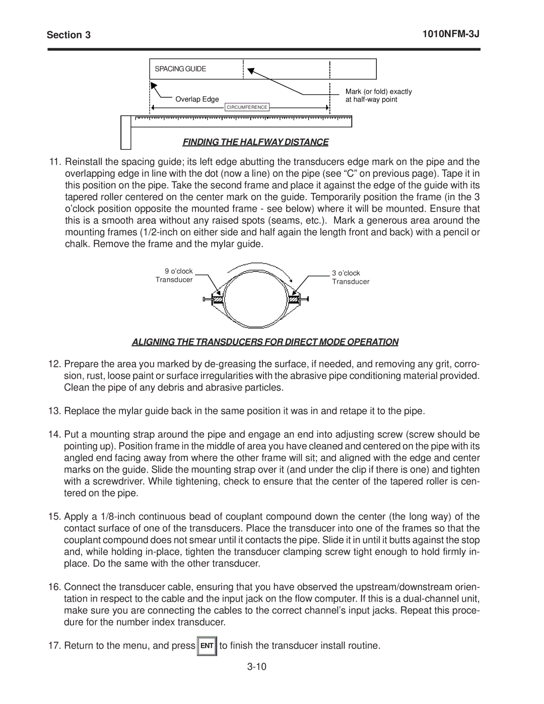
FINDING THE HALFWAY DISTANCE
11.Reinstall the spacing guide; its left edge abutting the transducers edge mark on the pipe and the overlapping edge in line with the dot (now a line) on the pipe (see “C” on previous page). Tape it in this position on the pipe. Take the second frame and place it against the edge of the guide with its tapered roller centered on the center mark on the guide. Temporarily position the frame (in the 3 o’clock position opposite the mounted frame - see below) where it will be mounted. Ensure that this is a smooth area without any raised spots (seams, etc.). Mark a generous area around the mounting frames
9 o’clock |
|
|
|
| |
9 o’clock |
| 33o’clocko’clock |
Transducer |
| |
Transducer |
| Transd r |
|
| Transducer |
|
|
|
ALIGNING THE TRANSDUCERS FOR DIRECT MODE OPERATION
12.Prepare the area you marked by
13.Replace the mylar guide back in the same position it was in and retape it to the pipe.
14.Put a mounting strap around the pipe and engage an end into adjusting screw (screw should be pointing up). Position frame in the middle of area you have cleaned and centered on the pipe with its angled end facing away from where the other frame will sit; and aligned with the edge and center marks on the guide. Slide the mounting strap over it (and under the clip if there is one) and tighten with a screwdriver. While tightening, check to ensure that the center of the tapered roller is cen- tered on the pipe.
15.Apply a
16.Connect the transducer cable, ensuring that you have observed the upstream/downstream orien- tation in respect to the cable and the input jack on the flow computer. If this is a
17. Return to the menu, and press
ENT
to finish the transducer install routine.