Siemens SITRANS FUS1010 NEMA-4X/ IP 65 manual Aux Io1 Aux Io2 Aux Io3 Aux Io4

Models: SITRANS FUS1010 NEMA-4X/ IP 65

1 232
Download 232 pages 51.98 Kb
Page 12
Image 12

Manual Addendum

1010FMA-14


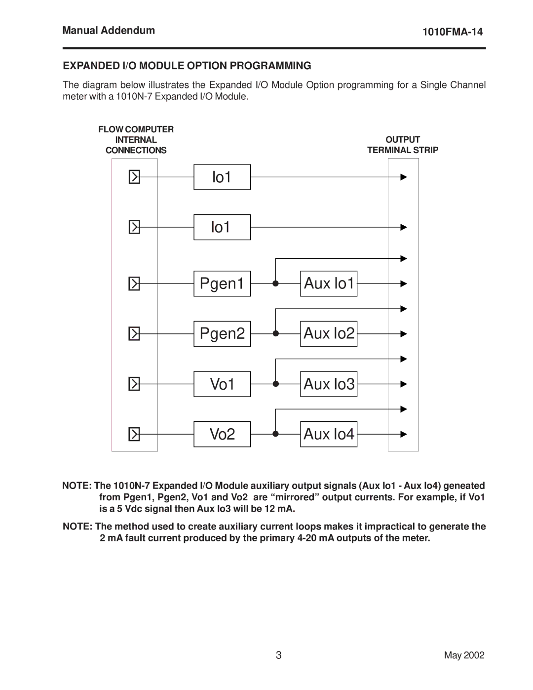
EXPANDED I/O MODULE OPTION PROGRAMMING

The diagram below illustrates the Expanded I/O Module Option programming for a Single Channel meter with a 1010N-7 Expanded I/O Module.

FLOW COMPUTER

INTERNAL

CONNECTIONS

`


Io1

`


Io1

`


Pgen1

`


Pgen2

`


Vo1

`


Vo2


OUTPUT

TERMINAL STRIP

zAux Io1

zAux Io2

zAux Io3

zAux Io4

NOTE: The 1010N-7 Expanded I/O Module auxiliary output signals (Aux Io1 - Aux Io4) geneated from Pgen1, Pgen2, Vo1 and Vo2 are “mirrored” output currents. For example, if Vo1 is a 5 Vdc signal then Aux Io3 will be 12 mA.

NOTE: The method used to create auxiliary current loops makes it impractical to generate the 2 mA fault current produced by the primary 4-20 mA outputs of the meter.

3

May 2002

Page 12
Image 12
Siemens SITRANS FUS1010 NEMA-4X/ IP 65 manual Aux Io1 Aux Io2 Aux Io3 Aux Io4, Expanded I/O Module Option Programming