Section 1 | ||
|
|
|
| EXPLANATION OF THE | |
|
|
|
Menu Prompt Line | When you select a menu cell, a highlighted text prompt appears on the top of | |
| the screen to explain the function of the cell. | |
Current Selected | [2 Channel] indicates Dual Channel meter operating mode selected. | |
Meter Type |
|
|
Selected Channel | The [1] indicates that measurement Channel 1 is currently selected. |
|
Highlighted Menu | The menu cursor (highlight bar) shows where you are currently working by |
|
Cell | reversing the display colors for that cell (white type on black). | |
Highlighted Data | The | |
| <Right Arrow> provides access to an option list or numeric field where you | |
| can change the current value as required. | |
Menu Cell | A menu cell is an individual location within a menu (in this case Pipe Data) |
|
| that stores a parameter (either a numeric entry or an option list selection. | |
Menu Cell Data | The | |
| menu cell. The Pipe Data Menu includes option list items and numeric entries. | |
Current Selected | The highlighted bar at the bottom of the screen shows the name of the menu |
|
Menu | that you are accessing (e.g., Pipe Data). | |
1.7HOW TO USE THE INSTALLATION MENU
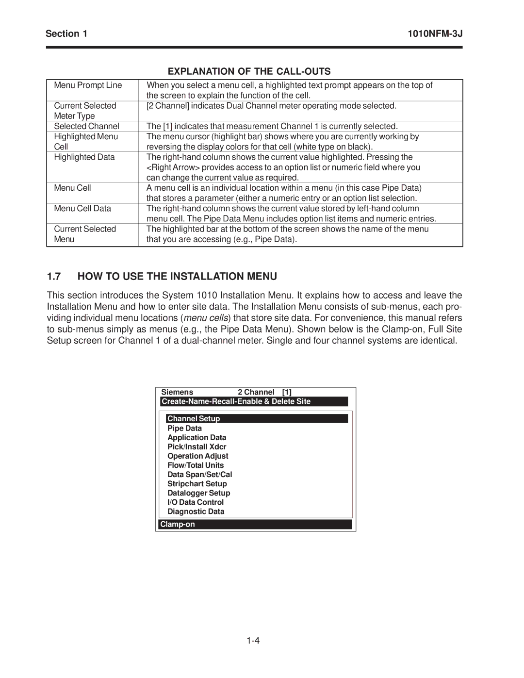
This section introduces the System 1010 Installation Menu. It explains how to access and leave the Installation Menu and how to enter site data. The Installation Menu consists of
Siemens2 Channel [1]
Create-Name-Recall-Enable & Delete Site
Channel Setup
Pipe Data
Application Data
Pick/Install Xdcr
Operation Adjust
Flow/Total Units
Data Span/Set/Cal
Stripchart Setup
Datalogger Setup
I/O Data Control
Diagnostic Data
