Siemens SITRANS FUS1010 NEMA-4X/ IP 65 Site Setup Considerations for 1010/1020N Blind Systems

Models: SITRANS FUS1010 NEMA-4X/ IP 65

1 232
Download 232 pages 51.98 Kb
Page 206
Image 206

Appendix

1010NFM-3J


APPENDIX B

SITE SETUP CONSIDERATIONS FOR 1010/1020N BLIND SYSTEMS

Siemens offers an economical “blind” 1010/1020 NEMA system (without a local keypad and graphic display screen). This supplement describes the hardware and software requirements for program- ming these models. Site setup for a blind unit requires a PC connected to the RS-232 serial port. These models include a serial interface cable for this purpose. The serial interface cable includes 9- pin and 25-pin connectors to accommodate both types of IBM-compatible serial ports. A PC commu- nication program such as Terminal (Windows 3.x) or HyperTerminal (Windows 95/98/NT/2000/XP) serves as the data entry interface. These programs reproduce the menu screens that would appear on the system’s graphic screen. In fact, the example screens in this manual are actual HyperTerminal screen captures. Once the serial interface is established, the site setup procedure for blind and graphic display systems are identical. You could choose to program a graphic display system using a PC and a communications program. However, note that for models with a local display screen, the serial interface cable is an option.

NOTE: You can use a DOS-based communications program also. Make sure that your PC is loading the ANSI.SYS driver via your Config.sys file. Set the program’s RS-232 param- eters to match those of the flowmeter (see HyperTerminal example screen on the fol- lowing pages).

NOTE: Many newer Laptop PC’s are not equipped with serial ports, having USB ports only. These PC’s will require a USB RS-232 adaptor that can be purchased commercially. Not all of these adaptors are suitable. Siemens has found the best performance is achieved with the adaptor from Radio Shack, (Part# 26-183).

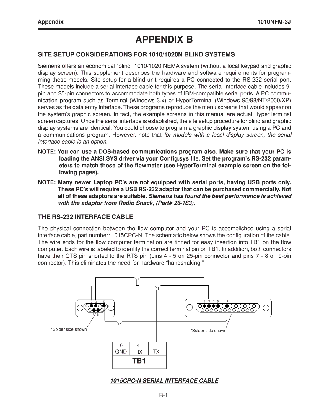
THE RS-232 INTERFACE CABLE

The physical connection between the flow computer and your PC is accomplished using a serial interface cable, part number: 1015CPC-N. The schematic below shows the configuration of the cable. The wire ends for the flow computer termination are tinned for easy insertion into TB1 on the flow computer. Each wire is labeled to identify the correct terminal pin on TB1. In addition, both connectors have their CTS pin shorted to the RTS pin (pins 4 - 5 on 25-pin connector and pins 7 - 8 on 9-pin connector). This eliminates the need for hardware “handshaking.”

2

3

5

2

3

4

5

7


7

8


*Solder side shown

*Solder side shown

6 4 1

GND RX TX

TB1

1015CPC-N SERIAL INTERFACE CABLE

B-1

Page 206
Image 206
Siemens SITRANS FUS1010 NEMA-4X/ IP 65 Site Setup Considerations for 1010/1020N Blind Systems, RS-232 Interface Cable