Section 7 | |
|
|
7.13REFLEXOR DIAGNOSTIC DATA
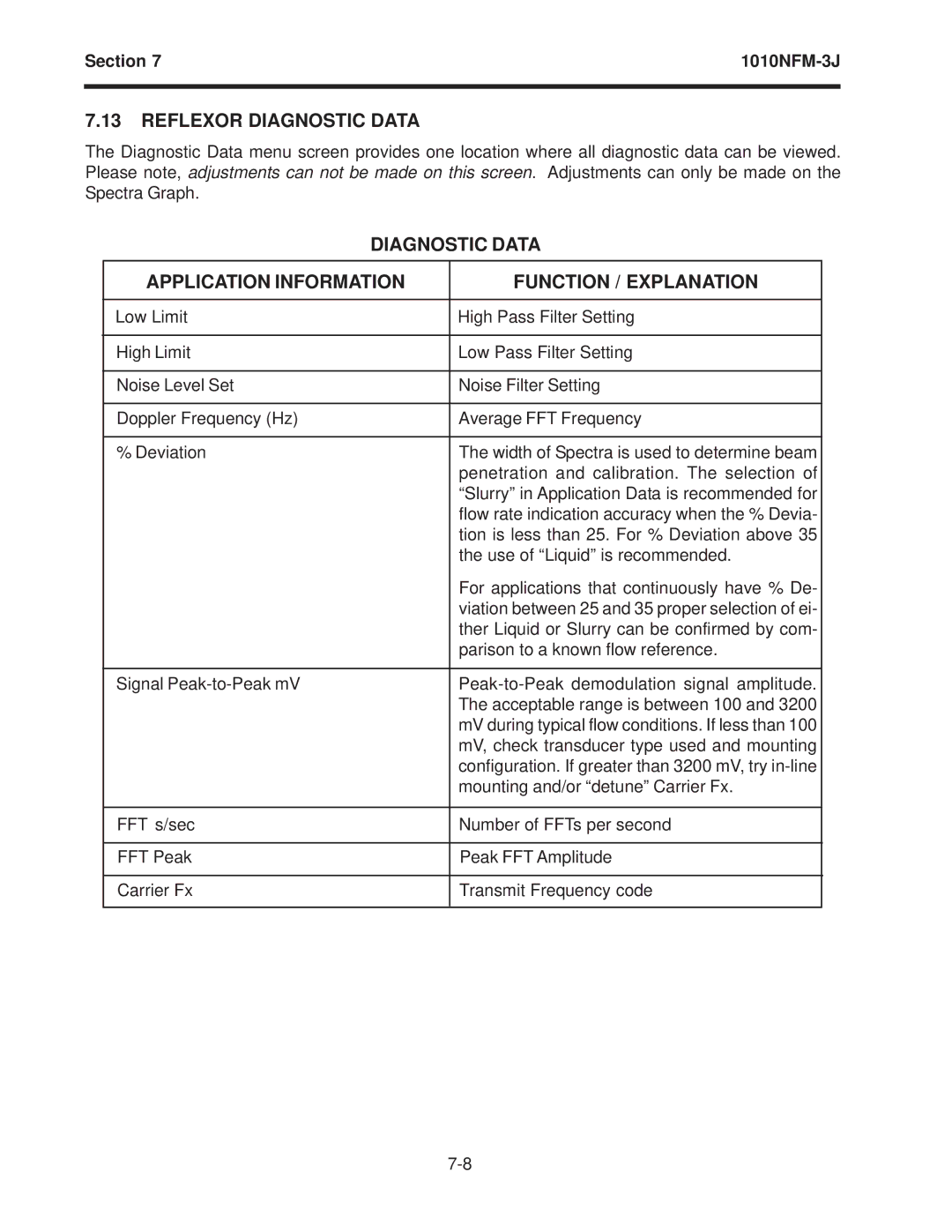
The Diagnostic Data menu screen provides one location where all diagnostic data can be viewed. Please note, adjustments can not be made on this screen. Adjustments can only be made on the Spectra Graph.
DIAGNOSTIC DATA
APPLICATION INFORMATION | FUNCTION / EXPLANATION |
|
|
Low Limit | High Pass Filter Setting |
|
|
High Limit | Low Pass Filter Setting |
|
|
Noise Level Set | Noise Filter Setting |
|
|
Doppler Frequency (Hz) | Average FFT Frequency |
|
|
% Deviation | The width of Spectra is used to determine beam |
| penetration and calibration. The selection of |
| “Slurry” in Application Data is recommended for |
| flow rate indication accuracy when the % Devia- |
| tion is less than 25. For % Deviation above 35 |
| the use of “Liquid” is recommended. |
| For applications that continuously have % De- |
| viation between 25 and 35 proper selection of ei- |
| ther Liquid or Slurry can be confirmed by com- |
| parison to a known flow reference. |
|
|
Signal | |
| The acceptable range is between 100 and 3200 |
| mV during typical flow conditions. If less than 100 |
| mV, check transducer type used and mounting |
| configuration. If greater than 3200 mV, try |
| mounting and/or “detune” Carrier Fx. |
|
|
FFT s/sec | Number of FFTs per second |
|
|
FFT Peak | Peak FFT Amplitude |
|
|
Carrier Fx | Transmit Frequency code |
|
|