Section 3 | |
|
|
Chain
Tension
Chain Tension
Screw
Screw
Tensionnsion ScrewScrew
Hookok
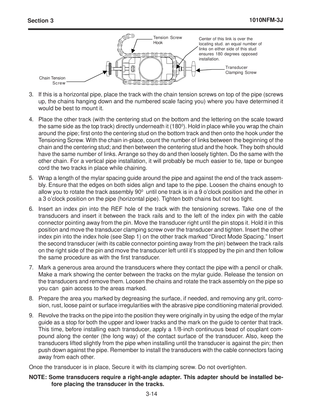
Center of this link is over the Center of this link is over the locating stud. an equal number of locating stud. An equal number of links on either side of this stud links on either side of this stud ensures 180 degrees opposed ensures 180° opposed installation. installation.
XdcrTransducer
![]() Clampinglamping Screw
Clampinglamping Screw
Screw
3.If this is a horizontal pipe, place the track with the chain tension screws on top of the pipe (screws up, the chains hanging down and the numbered scale facing you) where you have determined it would be best to mount it.
4.Place the other track (with the centering stud on the bottom and the lettering on the scale toward the same side as the top track) directly underneath it (1800). Hold in place while you wrap the chain around the pipe; first onto the centering stud on the bottom track and then onto the hook under the Tensioning Screw. With the chain
5.Wrap a length of the mylar spacing guide around the pipe and against the end of the track assem- bly. Ensure that the edges on both sides align and tape to the pipe. Loosen the chains enough to allow you to rotate the track assembly 900 until one track is in a 9 o’clock position and the other in a 3 o’clock position on the pipe (horizontal pipe). Tighten both chains but not too tight.
6.Insert an index pin into the REF hole of the track with the tensioning screws. Take one of the transducers and insert it between the track rails and to the left of the index pin with the cable connector pointing away from the pin. Move the transducer right until the pin stops it. Hold it in this position and move the transducer clamping screw over the transducer and tighten. Insert the other index pin into the index hole (see Step 1) on the other track marked “Direct Mode Spacing.” Insert the second transducer (with its cable connector pointing away from the pin) between the track rails on the right side of the pin and move the transducer left until it’s stopped by the pin and then follow the same procedure as with the first transducer.
7.Mark a generous area around the transducers where they contact the pipe with a pencil or chalk. Make a mark showing the center between the tracks on the mylar guide. Release the tension on the transducers and remove them. Loosen the chains and rotate the track assembly on the pipe so you can gain access to the areas marked.
8.Prepare the area you marked by degreasing the surface, if needed, and removing any grit, corro- sion, rust, loose paint or surface irregularities with the abrasive pipe conditioning material provided.
9.Revolve the tracks on the pipe into the position they were originally in by using the edge of the mylar guide as a stop for both the upper and lower tracks and the mark on the guide to center that track. This time, before installing each transducer, apply a
Once the transducer is in place, Secure it with its clamping screw. Do not overtighten.
NOTE: Some transducers require a
