Section 2 |
|
|
| ||||
|
|
|
|
|
|
|
|
|
|
|
|
|
|
|
|
|
|
| Siemens | 2 Channel | [1] Channel 1 |
| |
|
| Current Reynolds number |
|
| |||
|
|
|
|
|
|
|
|
|
|
| Temp 1 |
| 78.5 |
|
|
|
|
| Temp 2 |
| 50.0 |
|
|
|
|
| Reynolds # |
| 318017 |
|
|
|
|
| Specific Gravity | 1.000 S.G. |
|
| |
|
|
| Viscosity cP |
| 1.000 cP |
|
|
|
|
| Pressure |
| 14.5 PSIA |
|
|
|
|
| Viscosity cS |
| 1.000 cS |
|
|
|
|
|
|
|
|
| |
|
|
|
|
|
|
|
|
|
| Liquid Data |
|
|
|
| |
|
|
|
|
|
|
|
|
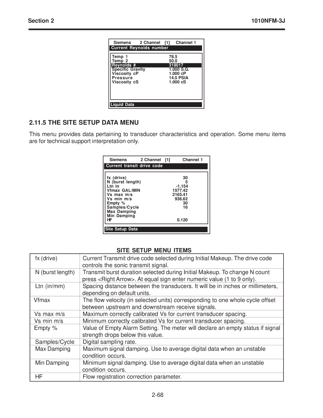
2.11.5 THE SITE SETUP DATA MENU
This menu provides data pertaining to transducer characteristics and operation. Some menu items are for technical support interpretation only.
| Siemens | 2 Channel [1] | Channel 1 |
|
| Current transit drive code |
|
| |
|
|
|
|
|
| fx (drive) |
| 30 |
|
| N (burst length) | 5 |
| |
| Ltn in |
|
| |
| Vfmax GAL/MIN |
| 1577.42 |
|
| Vs max m/s |
| 2165.41 |
|
| Vs min m/s |
| 936.62 |
|
| Empty % |
| 30 |
|
| Samples/Cycle |
| 16 |
|
| Max Damping |
|
|
|
| Min Damping |
| 0.120 |
|
| HF |
|
| |
|
|
|
|
|
| Site Setup Data |
|
|
|
|
|
|
|
|
| SITE SETUP MENU ITEMS | |
fx (drive) | Current Transmit drive code selected during Initial Makeup. The drive code | |
| controls the sonic transmit signal. | |
N (burst length) | Transmit burst duration selected during Initial Makeup. To change N count | |
| press <Right Arrow>. At equal sign enter numeric value (1 to 9 only). | |
Ltn (in/mm) | Spacing distance between the transducers. It will be in inches or millimeters, | |
| depending on default units. | |
Vfmax | The flow velocity (in selected units) corresponding to one whole cycle offset | |
| between upstream and downstream receive signals. | |
Vs max m/s | Maximum correctly calibrated Vs for current transducer spacing. | |
Vs min m/s | Minimum correctly calibrated Vs for current transducer spacing. | |
Empty % | Value of Empty Alarm Setting. The meter will declare an empty status if signal | |
| strength drops below this value. | |
Samples/Cycle | Digital sampling rate. | |
Max Damping | Maximum signal damping. Use to average digital data when an unstable |
|
| condition occurs. | |
Min Damping | Minimum signal damping. Use to average digital data when an unstable | |
| condition occurs. | |
HF | Flow registration correction parameter. | |
