Section 2 |
|
|
| ||
|
|
|
|
|
|
| THE DATA SPAN/SET/CAL MENU STRUCTURE |
|
| ||
| Data Span/Set/Cal | Span Data | Max Flow (Units) | x.xxx (numeric entry) |
|
|
|
| Min Flow (Units) | x.xxx (numeric entry) |
|
|
|
| Max Vs m/s | x.xxx (numeric entry) |
|
|
|
| Min Vs m/s | x.xxx (numeric entry) |
|
|
|
| Max S.G. | x.xxx (numeric entry) |
|
|
|
| Min S.G. | x.xxx (numeric entry) |
|
|
|
| Max Viscosity cS | x.xxx (numeric entry) |
|
|
|
| Min Viscosity | x.xxx (numeric entry) |
|
|
|
| Max Temperature | x.xxx (numeric entry) |
|
|
|
| Min Temperature | x.xxx (numeric entry) |
|
|
| Set Alarm Level | High Flow (Units) | x.xxx (numeric entry) |
|
|
|
| Low Flow (Units) | x.xxx (numeric entry) |
|
|
|
| High S.G. | x.xxx (numeric entry) |
|
|
|
| Low S.G. | x.xxx (numeric entry) |
|
|
|
| High Viscosity cS | x.xxx (numeric entry) |
|
|
|
| Low Viscosity cS | x.xxx (numeric entry) |
|
|
|
| High Temperature | x.xxx (numeric entry) |
|
|
|
| Low Temperature | x.xxx (numeric entry) |
|
|
|
| Interface Vs m/s | x.xxx (numeric entry) |
|
|
|
| Aeration % | x.xxx (numeric entry) |
|
|
|
| Makeup Latch | Off |
|
|
|
|
| On |
|
|
| Calibrate Flowrate | Intrinsic |
|
|
|
|
| Kc | Numeric entry |
|
|
|
| Multipoint | Point # | xx (numeric entry) |
|
|
|
| Indicated Rate | x.xxx (numeric entry) |
|
|
|
| % Correction | x.xxx (numeric entry) |
|
|
|
|
|
|
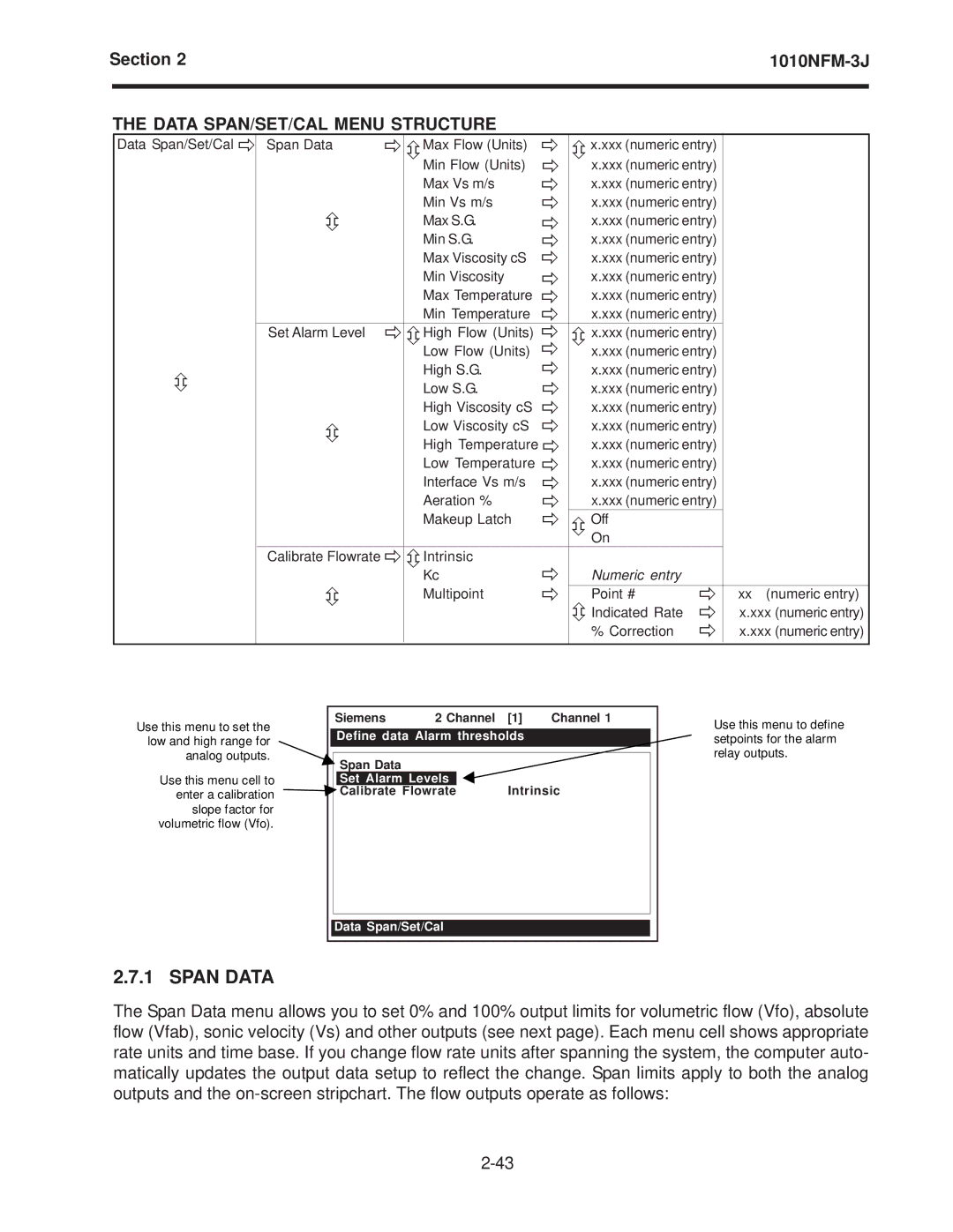
Use this menu to set the | Siemens | 2 Channel | [1] | Channel 1 | ||
low and high range for | Define data Alarm thresholds |
| ||||
analog outputs. |
|
|
|
|
|
|
| Span Data |
|
|
|
| |
|
|
|
|
|
| |
Use this menu cell to |
| Set Alarm Levels |
| Intrinsic | ||
enter a calibration |
| Calibrate Flowrate |
| |||
slope factor for |
|
|
|
|
|
|
volumetric flow (Vfo). |
|
|
|
|
|
|
|
|
|
|
|
|
|
Data Span/Set/Cal
Use this menu to define setpoints for the alarm relay outputs.
2.7.1 SPAN DATA
The Span Data menu allows you to set 0% and 100% output limits for volumetric flow (Vfo), absolute flow (Vfab), sonic velocity (Vs) and other outputs (see next page). Each menu cell shows appropriate rate units and time base. If you change flow rate units after spanning the system, the computer auto- matically updates the output data setup to reflect the change. Span limits apply to both the analog outputs and the
