Section 3 | |
|
|
zUsing a
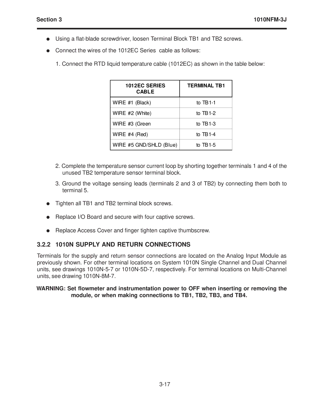
zConnect the wires of the 1012EC Series cable as follows:
1.Connect the RTD liquid temperature cable (1012EC) as shown in the table below:
1012EC SERIES | TERMINAL TB1 |
CABLE |
|
|
|
WIRE #1 (Black) | to |
|
|
WIRE #2 (White) | to |
|
|
WIRE #3 (Green | to |
|
|
WIRE #4 (Red) | to |
|
|
WIRE #5 GND/SHLD (Blue) | to |
|
|
2.Complete the temperature sensor current loop by shorting together terminals 1 and 4 of the unused TB2 temperature sensor terminal block.
3.Ground the voltage sensing leads (terminals 2 and 3 of TB2) by connecting them both to terminal 5.
zTighten all TB1 and TB2 terminal block screws.
zReplace I/O Board and secure with four captive screws.
zReplace Access Cover and finger tighten captive thumbscrew.
3.2.2 1010N SUPPLY AND RETURN CONNECTIONS
Terminals for the supply and return sensor connections are located on the Analog Input Module as previously shown. For other terminal locations on System 1010N Single Channel and Dual Channel units, see drawings
WARNING: Set flowmeter and instrumentation power to OFF when inserting or removing the module, or when making connections to TB1, TB2, TB3, and TB4.