Section 1 | ||
|
|
|
ment task. User output data, however, is mostly reserved for the virtual or system channel. This in- cludes the totalizer functions. Analog data is largely reserved for the virtual or system channel as well as the totalizer functions, analog outputs and datalogger. In some instances, access is also provided to the path channel’s data in order to facilitate the gathering of diagnostic information; thus minimizing menu clutter, but preserving as much functionality as practicable. Totalizer control via
Selecting A Meter Type
The following example explains how to select a
NOTE: If you have a
As shown in the steps below, selecting this mode only requires |
| key presses. This |
is because ![]() ENT
ENT![]() to select it.
to select it.
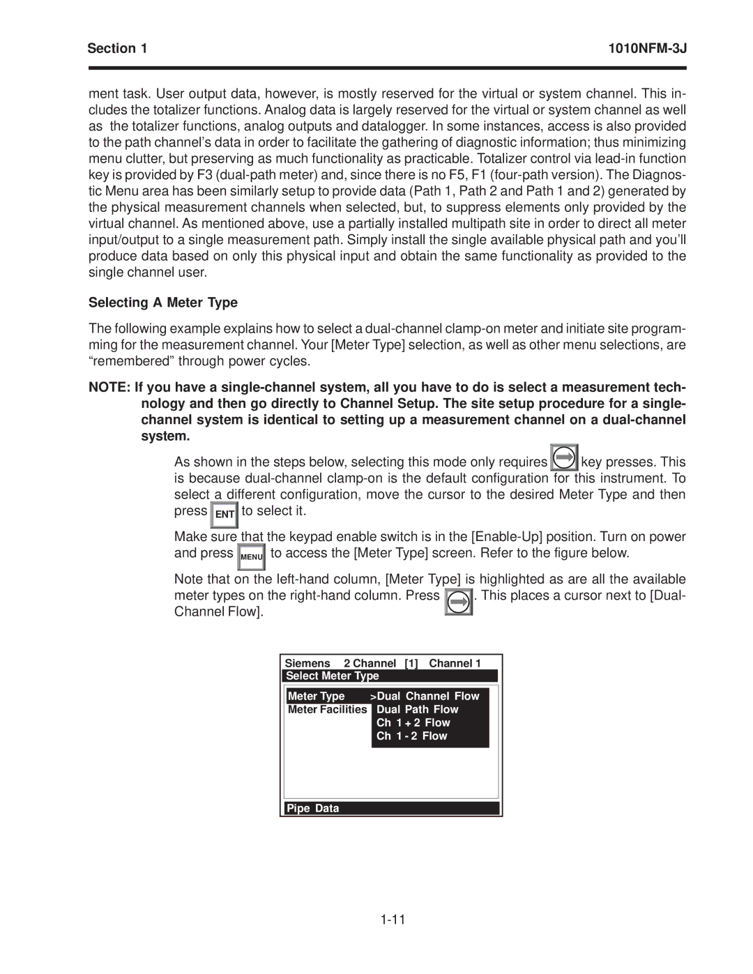
Make sure that the keypad enable switch is in the ![]()
![]() MENU
MENU![]() to access the [Meter Type] screen. Refer to the figure below.
to access the [Meter Type] screen. Refer to the figure below.
Note that on the
meter types on the |
| . This places a cursor next to [Dual- | |||||||||
| |||||||||||
Channel Flow]. |
|
|
|
|
|
|
|
| |||
|
|
|
|
|
|
|
| ||||
|
|
|
|
|
| ||||||
|
| Siemens 2 Channel | [1] Channel 1 | ||||||||
|
| Select Meter Type |
|
|
|
|
|
| |||
|
|
|
|
|
|
|
|
|
|
|
|
|
|
| Meter Type | >Dual Channel Flow |
|
|
| ||||
|
|
| Meter Facilities |
| Dual Path Flow |
|
|
|
| ||
|
|
|
|
| Ch 1 | + 2 Flow |
|
|
|
| |
|
|
|
|
| Ch 1 | - 2 Flow |
|
|
|
| |
|
|
|
|
|
|
|
|
|
|
|
|
Pipe Data
