Section 6 | |
|
|
6.3HOW TO SET UP SYSTEM 1010 FOR FLOW TUBE OPERATION
The example in this section shows how to set up channel 1 of a 1010 dual channel system for use with a 1011FT stainless steel Flow Tube. Note that Series 1010
6.3.1 OVERVIEW
Setting up the measurement channel for Flow Tube operation consists of the following tasks:
•Select a Meter Type (in this case Dual Channel Flow).
•Select a channel to install the flow tube (e.g., Channel 1).
•Set Kc calibration (slope correction) indicated on Flow Tube tag. (Note: Programmed Kc must match offset error on plastic Kc tag to get accurate flow tube readings. See paragraph 2.7.3 Calibrate Flow Rate.)
•Create a site setup to store the flow tube installation parameters.
•Enter liquid Parameters (optional, default = water@68°F).
•Complete the Flow Tube install procedure.
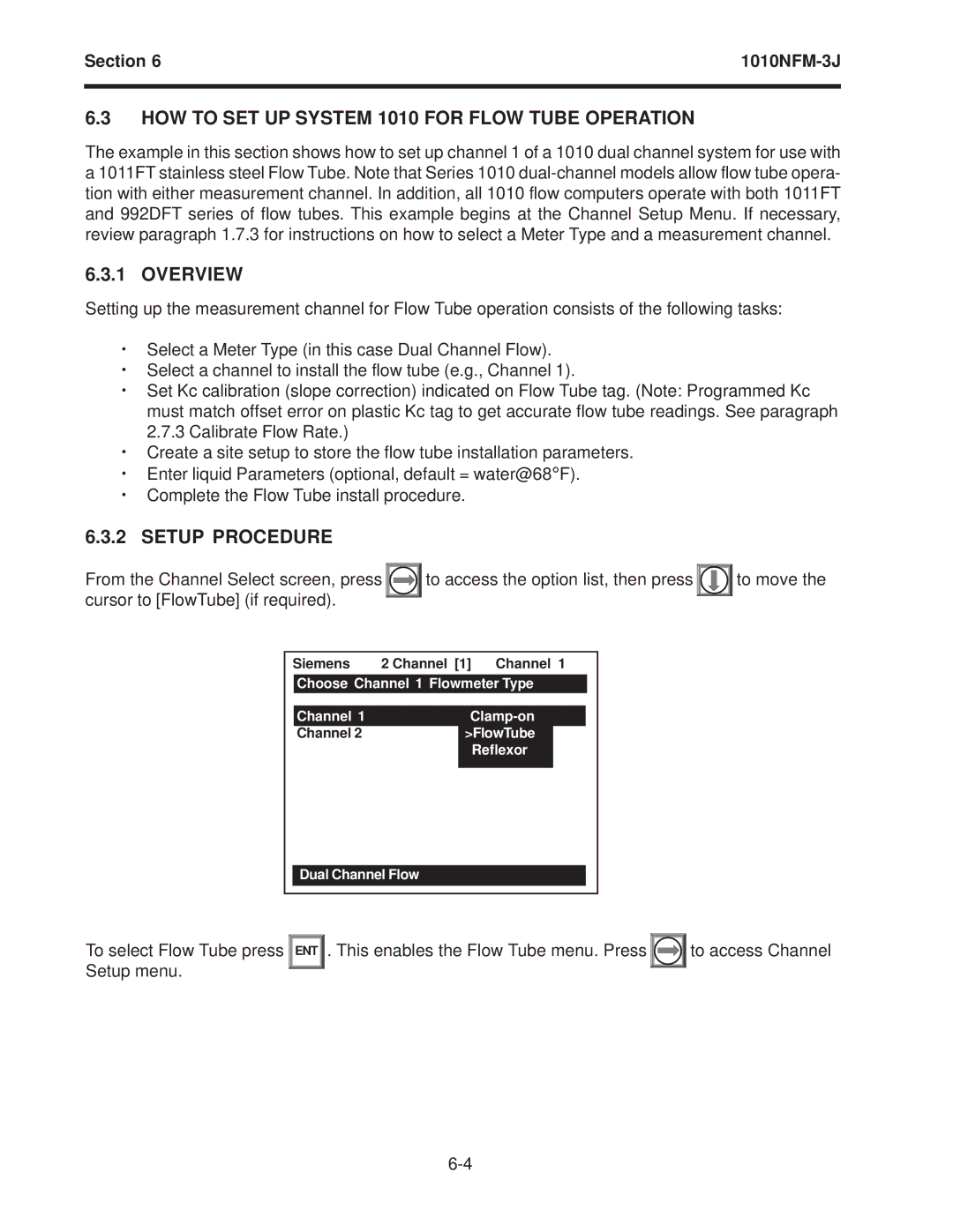
6.3.2SETUP PROCEDURE
From the Channel Select screen, press |
| to access the option list, then press |
| to move the | |||||||
cursor to [FlowTube] (if required). |
|
|
|
|
|
|
|
|
| ||
|
|
|
|
|
|
|
|
| |||
|
|
|
|
|
|
| |||||
| Siemens | 2 Channel [1] Channel 1 |
|
| |||||||
|
| Choose Channel 1 Flowmeter Type |
|
|
|
| |||||
|
|
|
|
|
|
|
|
|
|
|
|
|
| Channel 1 |
|
|
|
|
|
|
| ||
|
| Channel 2 |
|
|
| >FlowTube |
|
|
|
|
|
|
|
|
|
|
| Reflexor |
|
|
|
|
|
|
|
|
|
|
|
|
|
|
|
|
|
Dual Channel Flow
To select Flow Tube press | ENT | . This enables the Flow Tube menu. Press |
| to access Channel |
Setup menu. |
|
|
|
|
|
|
|
|