Section 3 | |
|
|
ChainCh in Tensioni
Screw
Screw
|
|
|
|
|
|
| Transducerr sducer |
| ||
UpstreamUpstre |
|
|
|
| Clampingl i ScrewScrew | Downstream | ||||
Transduc |
|
|
|
|
|
| Downstream Xdcr | |||
|
|
|
|
|
| |||||
Transducer |
|
|
|
|
|
| Transducer | |||
|
|
|
|
|
|
|
|
|
|
|
|
|
|
|
|
|
|
|
|
|
|
|
|
|
|
|
|
|
|
|
|
|
|
|
|
|
|
|
|
|
|
|
|
|
|
|
|
|
|
|
|
|
|
|
| FlowFlowÎ |
|
|
|
|
Reference Pin |
|
|
|
|
|
Reference Pin |
|
|
|
|
|
Shown Inserted |
|
|
|
| ll r |
Shown Inserted | TrackTrack Railil |
|
|
| |
| Number Index Pin | Roller | |||
| AssemblyAs bly | Nu | r | x pin | in |
| Shown | Inserted | Chain | ||
|
|
| inserted |
| |
Loopop ChainChainover overtensiontensionscrew hook
screw hook
Chain
Chain Tension
Tension
ScrewScr
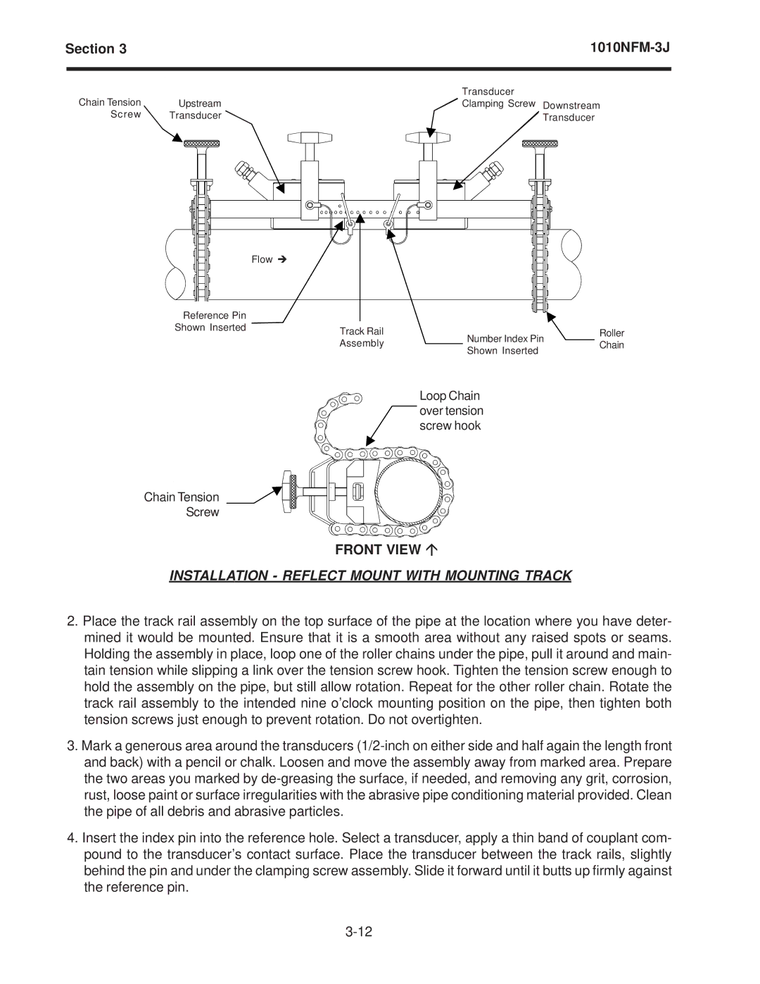
FRONT VIEW Ç
INSTALLATION - REFLECT MOUNT WITH MOUNTING TRACK
2.Place the track rail assembly on the top surface of the pipe at the location where you have deter- mined it would be mounted. Ensure that it is a smooth area without any raised spots or seams. Holding the assembly in place, loop one of the roller chains under the pipe, pull it around and main- tain tension while slipping a link over the tension screw hook. Tighten the tension screw enough to hold the assembly on the pipe, but still allow rotation. Repeat for the other roller chain. Rotate the track rail assembly to the intended nine o’clock mounting position on the pipe, then tighten both tension screws just enough to prevent rotation. Do not overtighten.
3.Mark a generous area around the transducers
4.Insert the index pin into the reference hole. Select a transducer, apply a thin band of couplant com- pound to the transducer’s contact surface. Place the transducer between the track rails, slightly behind the pin and under the clamping screw assembly. Slide it forward until it butts up firmly against the reference pin.