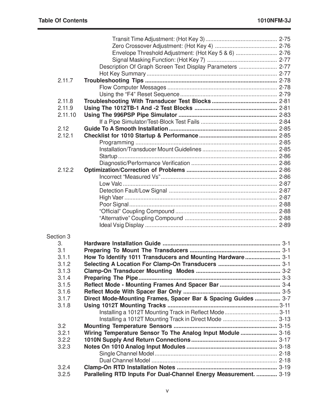
Table Of Contents | ||
|
|
|
| Transit Time Adjustment: (Hot Key 3) | |
| Zero Crossover Adjustment: (Hot Key 4) | |
| Envelope Threshold Adjustment: (Hot Key 5 & 6) | |
| Signal Masking Function: (Hot Key 7) | |
| Description Of Graph Screen Text Display Parameters | |
| Hot Key Summary | |
2.11.7 | Troubleshooting Tips | |
| Flow Computer Messages | |
| Using the “F4” Reset Sequence | |
2.11.8 | Troubleshooting With Transducer Test Blocks | |
2.11.9 | Using The | |
2.11.10 Using The 996PSP Pipe Simulator | ||
| If a Pipe | |
2.12 | Guide To A Smooth Installation | |
2.12.1 | Checklist for 1010 Startup & Performance | |
| Programming | |
| Installation/Transducer Mount Guidelines | |
| Startup | |
| Diagnostic/Performance Verification | |
2.12.2 | Optimization/Correction of Problems | |
| Incorrect “Measured Vs” | |
| Low Valc | |
| Detection Fault/Low Signal | |
| High Vaer | |
| Poor Signal | |
| “Official” Coupling Compound | |
| “Alternative” Coupling Compound | |
| Ideal Vsig Display | |
Section 3 |
|
|
3. | Hardware Installation Guide | |
3.1 | Preparing To Mount The Transducers | |
3.1.1 | How To Identify 1011 Transducers and Mounting Hardware | |
3.1.2 | Selecting A Location For | |
3.1.3 | ||
3.1.4 | Preparing The Pipe | |
3.1.5 | Reflect Mode - Mounting Frames And Spacer Bar | |
3.1.6 | Reflect Mode With Spacer Bar Only | |
3.1.7 | Direct | |
3.1.8 | Using 1012T Mounting Tracks | |
| Installing a 1012T Mounting Track in Reflect Mode | |
| Installing a 1012T Mounting Track in Direct Mode | |
3.2 | Mounting Temperature Sensors | |
3.2.1 | Wiring Temperature Sensor To The Analog Input Module | |
3.2.2 | 1010N Supply And Return Connections | |
3.2.3 | Notes On 1010 Analog Input Modules | |
| Single Channel Model | |
| Dual Channel Model | |
3.2.4 | ||
3.2.5 | Paralleling RTD Inputs For | |
v
