Section 3 | |
|
|
3.HARDWARE INSTALLATION GUIDE
3.1PREPARING TO MOUNT THE TRANSDUCERS
Installing the transducers is fairly straightforward. However, careful planning will avoid any snags that may delay the installation. Previously, based on the input you fed into the meter’s computer, it had recommended the transducers size, mounting option and spacing. With the transducers at hand, we are now ready to mount them. But first, some very important preliminary work must be done which consists of:
zSelecting a mounting option for your application
zSelecting a location on the pipe
zPreparing the pipe to accept the transducers
NOTE: When installing transducers, do not key in the V/M (Version/Modification) label number as the Transducer Size.
3.1.1 HOW TO IDENTIFY 1011 TRANSDUCERS AND MOUNTING HARDWARE
1011 series of universal transducers and mounting frames have the following
GOLD | SIZE ‘A’ | GREEN…………………SIZE ‘D’ |
BLUE | SIZE ‘B’ | BLACK…………………SIZE ‘E’ |
RED | SIZE ‘C’ |
|
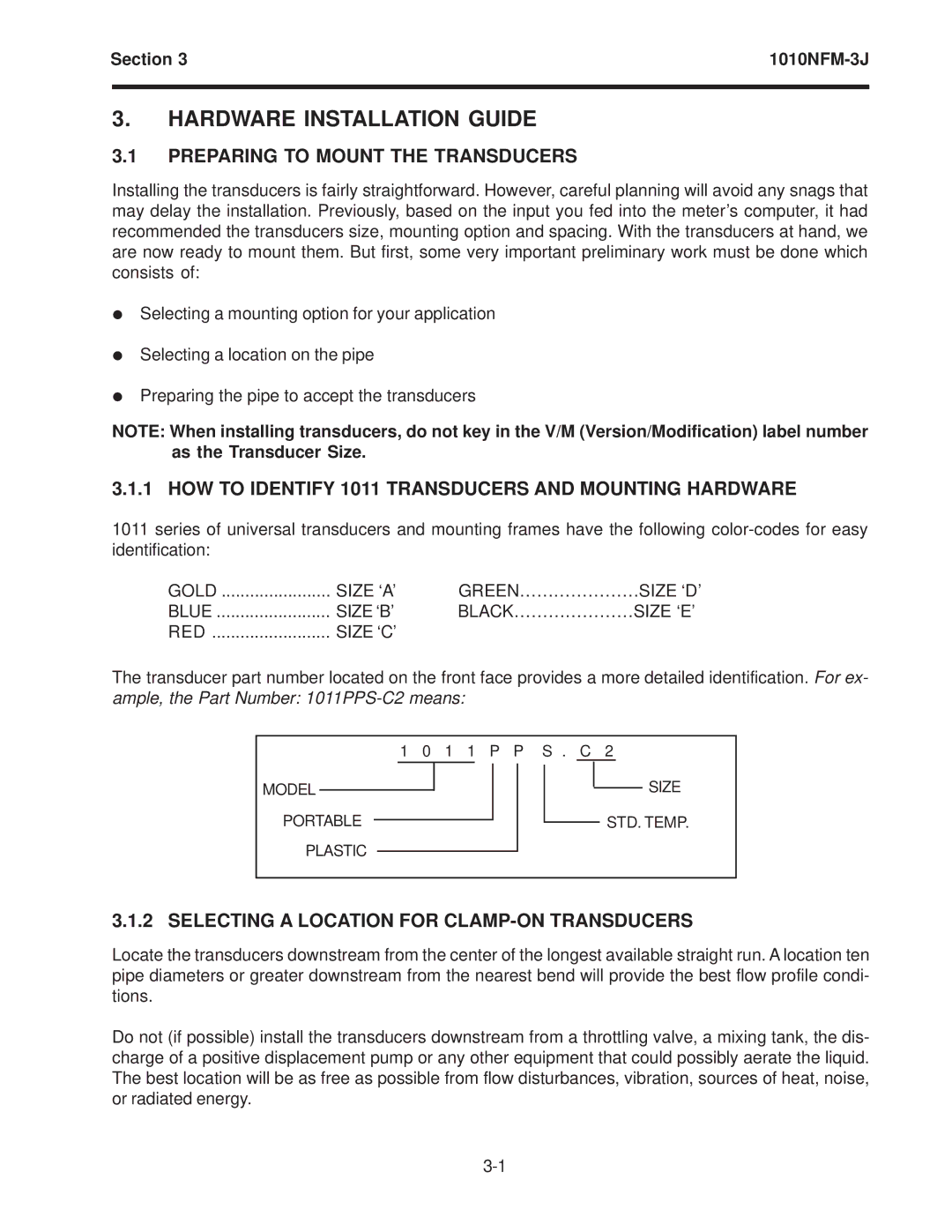
The transducer part number located on the front face provides a more detailed identification. For ex- ample, the Part Number:
1 0 1 1 P P S . C 2
MODEL
PORTABLE
PLASTIC
SIZE
STD. TEMP.
3.1.2 SELECTING A LOCATION FOR CLAMP-ON TRANSDUCERS
Locate the transducers downstream from the center of the longest available straight run. A location ten pipe diameters or greater downstream from the nearest bend will provide the best flow profile condi- tions.
Do not (if possible) install the transducers downstream from a throttling valve, a mixing tank, the dis- charge of a positive displacement pump or any other equipment that could possibly aerate the liquid. The best location will be as free as possible from flow disturbances, vibration, sources of heat, noise, or radiated energy.
