Section 2 | ||
|
|
|
2.11.8TROUBLESHOOTING WITH TRANSDUCER TEST BLOCKS
To resolve an apparent system malfunction, you have to determine whether the problem is due to equipment failure or an application condition. Our 1012 and 996 Transducer Test Blocks allow you to bench test the flow computer, transducers and their cables. If the system operates properly using the test block, then focus on application conditions as the source of the problem. Series A and B 1011 transducers use the
The
2.11.9USING THE 1012TB-1 AND 2 TEST BLOCKS
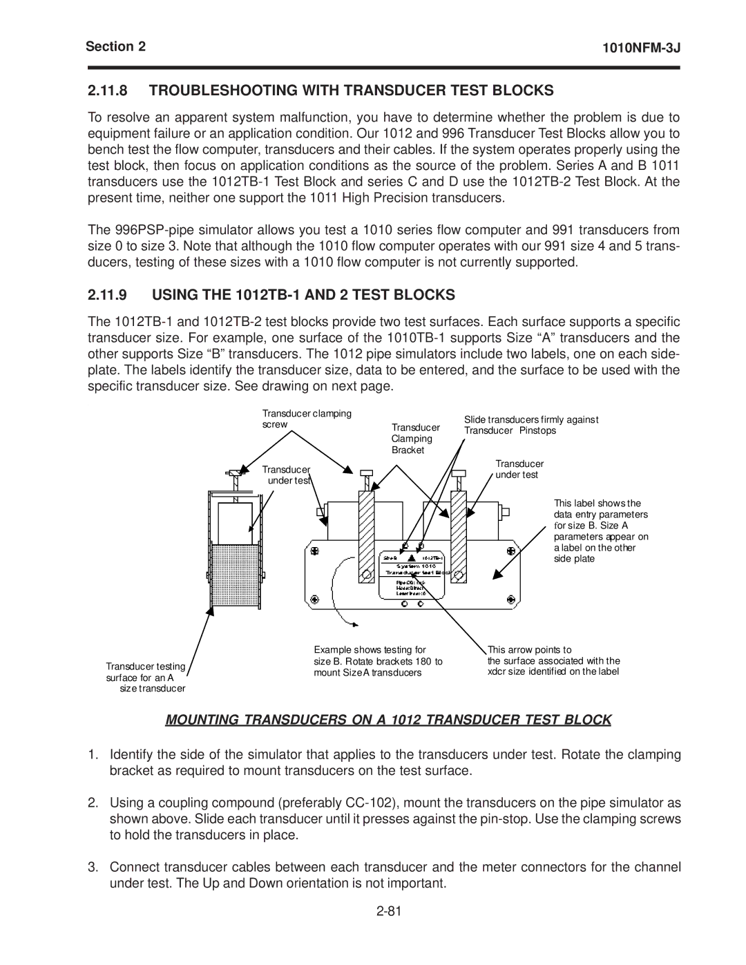
The
Transducer clamping
screwTransducer Clamping Bracket
Transducer under test
Slide transducers firmly against
Transducer Pinstops
Transducer under test
This label shows the data entry parameters for size B. Size A parameters appear on a label on the other side plate
Transducer testing surface for an A
size transducer
Example shows testing for | This arrow points to |
size B. Rotate brackets 180 to | the surface associated with the |
mount SizeA transducers | xdcr size identified on the label |
MOUNTING TRANSDUCERS ON A 1012 TRANSDUCER TEST BLOCK
1.Identify the side of the simulator that applies to the transducers under test. Rotate the clamping bracket as required to mount transducers on the test surface.
2.Using a coupling compound (preferably
3.Connect transducer cables between each transducer and the meter connectors for the channel under test. The Up and Down orientation is not important.