Appendix |
|
|
|
|
|
| |||
|
|
|
|
|
|
|
|
|
|
|
|
|
|
|
|
|
|
|
|
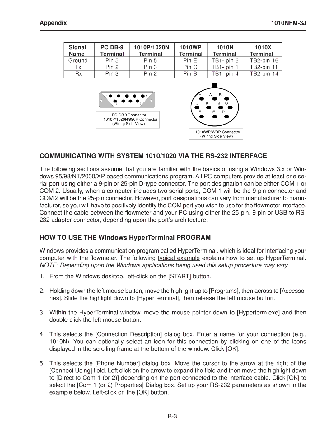
| Signal | PC | 1010P/1020N | 1010WP |
| 1010N | 1010X |
| |
| Name | Terminal | Terminal | Terminal |
| Terminal | Terminal |
| |
| Ground | Pin 5 | Pin 5 | Pin E | TB1- pin 6 |
|
| ||
| Tx | Pin 2 | Pin 3 | Pin C | TB1- pin 1 |
| |||
| Rx | Pin 3 | Pin 2 | Pin B | TB1- pin 4 |
| |||
|
|
|
|
|
|
|
|
|
|
|
|
|
|
|
|
|
|
|
|
1 ![]()
![]()
![]()
![]()
![]() 5
5
69
PC
(Wiring Side View)
H A B
G K J C
F E D
1010WP/WDP Connector (Wiring Side View)
COMMUNICATING WITH SYSTEM 1010/1020 VIA THE RS-232 INTERFACE
The following sections assume that you are familiar with the basics of using a Windows 3.x or Win- dows 95/98/NT/2000/XP based communications program. All PC computers provide at least one se- rial port using either a
HOW TO USE THE Windows HyperTerminal PROGRAM
Windows provides a communication program called HyperTerminal, which is ideal for interfacing your computer with the flowmeter. The following typical example explains how to set up HyperTerminal. NOTE: Depending upon the Windows applications being used this setup procedure may vary.
1.From the Windows desktop,
2.Holding down the left mouse button, move the highlight up to [Programs], then across to [Accesso- ries]. Slide the highlight down to [HyperTerminal], then release the left mouse button.
3.Within the HyperTerminal window, move the mouse pointer down to [Hyperterm.exe] and then
4.This selects the [Connection Description] dialog box. Enter a name for your connection (e.g., 1010N). You can optionally select an icon for this connection by clicking on one of the icons displayed in the scrolling frame at the bottom of the window. Click [OK].
5.This selects the [Phone Number] dialog box. Move the cursor to the arrow at the right of the [Connect Using] field. Left click on the arrow to expand the field and then move the highlight down to [Direct to Com 1 (or 2)] depending on the port connected to the interface cable. Click [OK] to select the [Com 1 (or 2) Properties] Dialog box. Set up your