3CRWX120695A, 3CRWX440095A
Wireless LAN Mobility System
3Com Corporation 350 Campus Drive Marlborough, MA USA
Contents
Set system location
Clear banner motd Clear history Clear prompt
Vlan Commands
147 Set ntp 148
131 Ping 132 Set arp 133 Set arp agingtime 134
142 Set ip ssh 143
144
183
169
Display location policy 185 Display mobility-profile
241
MAP Access Point Commands by Usage
228
234
261 Reset ap dap 264
254 Display dap unconfigured 256 Display radio-profile 257
327
311
319
326
345
335
Set spantree
337
373
Commands by Usage 393
369
Clear security acl 370 Clear security acl map 371
444
435
446
480
465 Set rf detect countermeasures
466
Set rfdetect ignore 467 Set rfdetect log 468
517
Commands by Usage 491 Clear log trace Clear trace 492
Fver 519 Help 520 Next 521 Reset 522 Test 523
496 Set trace sm 497
Register Your Product 527
Version
List conventions that are used throughout this guide
Conventions
„ Wireless LAN Switch and Controller Release Notes
„ Wireless LAN Switch Manager 3WXM Release Notes
Documentation
„ Document part number and revision on the title
Comments
Pddtechpubscomments@3com.com
„ Document title
About this Guide
Overview
Clear interface vlan-idip
Set enablepass
Clear fdb dynamic port port-list vlan vlan-id
Notation
Text Entry
Conventions
MAC Address
User Globs
Masks
Subnet Masks
Wildcard Masks
MAC Address Globs
Gives examples of user globs
User Globs
„ a single port number. For example
WX1200# set port enable
Vlan Globs
Matching Order for Globs
Operating systems
Command-Line
WX1200# reset port
Editing
WX1200# display i Tab
At your access level, type the help command. For example
Using CLI Help
WX1200# display i?
WX1200# display ip telnet
Understanding Command Descriptions
Set ap dap name command has the following complete syntax
WX1200# display ip ?
Understanding Command Descriptions
Using the COMMAND-LINE Interface
Syntax disable Defaults None
Commands by
Disable
To located commands in this chapter based on their use
Quit
Enable
Set enablepass
Access Commands
To located commands in this chapter based on their use
System Service Commands
„ display banner motd on
Banner with an empty banner by typing the following command
Clear banner motd
Clear history
Clear system
Clear prompt
Motd
Display banner
Base-information
Display
Display license
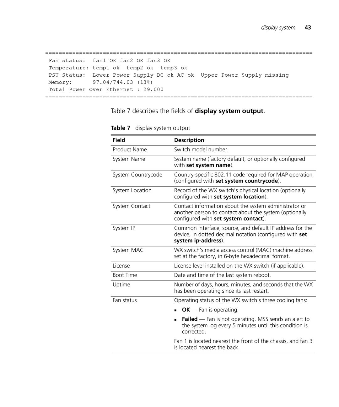
Shows system information
Defaults None Access All
Display system
„ set license on
Display system output
Describes the fields of display system output
Nvram size /SDRAM size percent of total
Help
WX switch
Syntax help
Syntax history
History
See Also „ clear history on
Syntax set confirm on off
Set confirm
See Also „ clear banner motd on „ display banner motd on
That might have a large impact on the network
WX4400# set confirm off
Set length
Examples To turn off these confirmation messages, type
WX4400# clear vlan red
Set license
Installs an upgrade license, for managing more MAPs
See Also „ display license on
Syntax set prompt string
Set prompt
Syntax set system contact string
Set system contact Stores a contact name for the WX switch
Set system
Countrycode
Country Code
Mobility Domain
Defaults The factory default country code is None
Using any set ap commands to configure a MAP
Ip-address
Syntax set system location string
See Also „ clear system on „ display system on
Syntax set system name string
„ set system contact on „ set system name on
System Service Commands
Locate commands in this chapter based on their use
Port Commands
„ set dap on
That are using the MAP
Clear dap
Removes a Distributed MAP
Clear port name Removes the name assigned to a port
Clear port-group
„ name name Name of the port group
See Also „ set port-groupon „ display port-groupon
Interface for the active link
Clear port
Preference
See Also „ display port status on „ set port name on
Port
Network port defaults
Clear port type
Network port
Counters
Display port
Describes the fields in the display port-group output
Display port-groupShows port group information
Output for display port-group
Syntax display port poe port-list
See Also „ clear port-groupon „ set port-groupon
Describes the fields in this display
Output for display port poe
Specified ports
Usage This command applies only to the WX4400
All four ports of a WX4400 switch
„ set port poe on
Syntax display port status port-list
Output for display port preference
WX1200# display port status
Output for display port status
„ set port speed on
Monitor port
See Also „ clear port type on
„ set port negotiation on
Key Controls for Monitor Port Counters Display
WX4400# monitor port counters
Output for monitor port counters
Correct length but contained an invalid
See Also „ display port counters on
Set dap
Reset port
Port Commands
Set dap
Set port
Examples The following command disables port
Fol1owing command reenables the port
Administratively disables or reenables a port
Single logical link
Configured together as a single logical link
With no spaces
See Also „ clear port name on „ display port status on
Name or number in other CLI commands
Set port name
See Also „ clear port-groupon „ display port-groupon
Set port poe
Set port negotiation
Result
WX1200# set port poe 4,5 enable
Following command enables PoE on ports 4
See Also „ set port type ap on „ set port type wired-authon
WX1200# set port poe 4,5 disable
Syntax set port speed port-list10 100 1000 auto
Set port speed
Changes the speed of a port
WX4400# set port preference 2 rj45
Set port trap
Set snmp trap command
Set port type ap
„ 11a 802.11a „ 11b 802.11b „ 11g 802.11g
Antenna model, use the following command
„ poe enable disable Power over Ethernet PoE state
Defaults All WX ports are network ports by default
STP
MAP Access Port Defaults
Set port type
Wired-auth
WX1200# set port type wired-auth 2 success change accepted
Wired Authentication Port Details
See Also „ clear port type on „ set port type ap on
Vlan Commands
WX4400# clear fdb static vlan blue success change accepted
Clear fdb
Deletes an entry from the forwarding database FDB
Syntax clear fdb perm static dynamic
„ display fdb on
Clear vlan
Port from the VLAN, make sure you specify the port number
Displays entries in the forwarding database
Following command completely removes Vlan marigold
See Also „ set vlan port on „ display vlan config on
Display fdb
WX4400# display fdb all
Output for display fdb
Agingtime
Describes the fields in the display fdb output
See Also „ clear fdb on
WX1200# display fdb agingtime
See Also „ set fdb agingtime on
Syntax display fdb count perm static dynamic
Station
Display roaming
See Also „ display roaming vlan on
Describes the fields in the display
Output for display roaming station
Syntax display roaming vlan
Output for display roaming vlan
WX4400# display roaming vlan
Syntax display tunnel
See Also „ display vlan config on
Display tunnel
Output for display tunnel
WX1200# display vlan config burgundy
Display vlan config
Output for display vlan config
Syntax display vlan config vlan-id
Adds a permanent or static entry to the forwarding database
Set fdb
Syntax set fdb perm static
See Also „ clear fdb on „ display fdb on
Creates a Vlan and assigns a number and name to it
Set vlan name
See Also „ display fdb agingtime on
Vlan 4094 is reserved for WebAAA
Set vlan port
Tunnel-affinity
Set vlan
See Also „ display roaming vlan on „ display vlan config on
To locate commands in this chapter based on their use
IP Services Commands
DNS
IP Services Commands by Usage
Removes an IP interface
Clear interface
Syntax clear interface vlan-idip
WX1200# clear ip dns domain
Access Enabled
History Introduced in MSS Version
See Also „ display ip alias on
„ set ip dns server on
Clear ip dns server
Clear ip route
„ set ip dns domain on
„ display ip route on
Clear ip telnet
„ set ip route on
Clear ntp server
Update-interval
Clear ntp
See Also „ clear ntp server on „ display ntp on
„ set ntp server on „ set ntp update-intervalon
Clear snmp trap
Receiver
Clear summertime
Examples To clear the system IP address, type the following
Command
Following command
Clear timezone
Shows the ARP table
Display arp
Display timedate on
Display timezone on
„ set arp agingtime on
„ set arp on
Syntax display interface vlan-id
Output for display interface
Shows the IP aliases configured on the wireless LAN switch
Display ip alias
See Also „ set interface on „ set interface status on
„ set ip alias on
Examples The following command displays the DNS information
Display ip dns
„ clear ip alias on
Syntax display ip https
Display ip https
Shows information about the Https management port
Output for display ip dns
WX4400# display ip https
Output for display ip https
WX4400# display ip route
Display ip route
Shows the IP route table
Syntax display ip route destination
FieldDescription
Output of display ip route
Syntax display ip telnet
Output for display ip telnet
WX4400 display ip telnet
Output for display ntp
Examples To display NTP information for a WX switch, type
Display ntp
Shows NTP client information
„ set ntp server on „ set summertime on „ set timezone on
Display snmp
Configuration
Shows Snmp settings on a wireless LAN switch
Examples To display Snmp settings on a WX switch, type
Output of display snmp configuration
WX1200# display summertime
Defaults There is no summertime offset by default
Summertime
Syntax display summertime
Syntax display timezone
WX1200# display timedate
WX4400# display timezone
„ set timedate on „ set timezone on
Defaults „ count
„ traceroute on
Set arp
WX1200# set arp agingtime
Following command disables ARP aging
See Also „ set arp agingtime on
Syntax set arp agingtime seconds
Set interface
Syntax set interface vlan-idstatus up down
WX1200# set interface mauve ip 10.10.20.10
See Also „ clear ip alias on „ display ip alias on
Aliases as shortcuts in CLI commands
Set ip alias
Set ip dns
WX1200# set ip dns domain example.com
Syntax set ip dns domain name
Syntax set ip dns server ip-addrprimary secondary
Set ip route
WX switch is also disabled
Adds a static route to the IP route table
Set ip route
Syntax set ip snmp server enable disable
Secure Shell SSH management traffic
See Also „ set ip ssh absolute-timeouton
Set ip ssh
„ clear snmp trap receiver on
Or idle
Absolute-timeout
„ set ip ssh idle-timeouton „ set ip ssh server on
Syntax set ip ssh absolute-timeout minutes
Also disabled
Idle-timeout
Set ip ssh server
Set ip telnet
WX4400# set ip telnet server enable success change accepted
Syntax set ip telnet server enable disable
Set ntp
Examples The following command enables the NTP client
Enables or disables the NTP client on a wireless LAN switch
Configures a wireless LAN switch to use an NTP server
From 16 through 1,024 seconds
RFC 1305, Network Time Protocol Version 3 Specification
Implementation and Analysis
NTP server
Community
Set snmp
Public and private
Sends an Snmp trap message to any network management system
„ enable Enables trap information to be sent
„ disable Disables the sending of trap information
„ all Enables or disables all traps
Snmp Trap Names
Defaults All traps are disabled by default Access Enabled
See Also „ clear snmp trap receiver on
Set snmp trap
IP Services Commands
Following
To PDT Pacific Daylight Time, type the following command
Values
Date is within the summertime period
„ time hhmmss System time, in hours, minutes, and seconds
Sets the time of day and date on the wireless LAN switch
Set timedate
„ date mmm dd yyyy System date
WX4400# set timedate date feb 29 2004 time
Set timezone
Time now is Sun Feb 29 2004, 235802 PST
Opens a Telnet client session with a remote device
Telnet
WX1200# set timezone PST
WX4400# telnet
See Also „ clear sessions on „ display sessions on
„ queries „ size „ ttl
Defaults
„ dnf Disabled „ no-dns- Disabled „ port
Traceroute
WX4400# traceroute server1
Error messages for traceroute
„ ping on
This chapter presents AAA commands alphabetically. Use to
Locate commands in this chapter based on their use
AAA Commands by Usage
Display accounting statistics on
WX4400# clear accounting dot1x Nin
Syntax clear accounting admin dot1x user-glob
Admin
Clear authentication
WX4400# clear authentication console Regina
Syntax clear authentication console user-glob
ConsoleConsole
Syntax clear authentication dot1x ssid ssid-namewired
Syntax clear authentication mac ssid ssid-namewired
Clear authentication Removes a MAC authentication rule. mac
Syntax clear authentication last-resort ssid ssid-namewired
WX4400# clear authentication last-resort wired
WX4400# clear authentication mac ssid thatcorp aabbcc
Clear authentication Removes a WebAAA rule. web
Syntax clear authentication web ssid ssid-namewired
Syntax clear location policy rule-number
See Also „ display aaa on „ set mac-usergroup attr on
Clear mac-user
„ display location policy on
„ set location policy on
Group
Clear mac-user attr
„ set mac-user attr on
Mac-usergroup
Clear
Mac-usergroup attr
Mac-user group command
„ clear mac-usergroup attr on
Clear user
Mobility-profile
See Also „ display aaa on
Clear user attr
Clear usergroup
Clear user group
Syntax clear usergroup group-name
„ group-name- Name of an existing user group
WX4400# clear usergroup cardiology success change accepted
Display aaa
Displays all current AAA settings
Time-Of-Day attribute from the group
Display aaa Output
Describes the fields that can appear in display aaa output
User’s password, and no global password is set
Statistics output
Stored in the local database on the WX switch
Display accounting
Statistics
Aaattyattr
Policy
Display location
„ clear location policy on
Set accounting
Admin console
Are sent
Authenticated by MAC authentication
Server when the user roams
Accesses the switch using Telnet or Web Manager
Authenticated by
AAA Commands
Set authentication
AAA Commands
Following methods in priority order. MSS applies multiple
Through the switch’s console
Completing logon
Globs on
For more information, see Usage
Syntax set authentication dot1x ssid ssid-namewired
AAA Commands
Set authentication dot1x
Success change accepted
Syntax set authentication last-resort
AAA Commands
Syntax set authentication mac
AAA Commands
Syntax set authentication web ssid ssid-namewired
AAA Commands
Set location policy
AAA Commands
Set location policy
WX4400# set location policy deny if user eq *.theirfirm.com
Tempvendora into Vlan kiosk1
Set mac-user
See Also „ clear mac-useron „ display aaa on
Authentication Attributes for Local Users
Filter-id outboundacl.out
Authentication Attributes for Local Users
YY/MM/DD-HHMM
Time-of-day
WX4400# set mac-user 010203040506 attr filter-id acl-03.in
Syntax set mac-usergroup
See Also „ clear mac-user attr on „ display aaa on
Syntax set mobility-profile name name port none all
See Also „ clear mac-usergroup attr on „ display aaa on
AAA Commands
„ set user attr on „ set usergroup on
Syntax set mobility-profile mode enable disable
29Jan04
Set user
See Also „ clear user on „ display aaa on
Orange
Set user attr
See Also „ clear user attr on „ display aaa on
Set usergroup
Set user group
„ clear user group on
Syntax set web-aaa enable disable
To add a user to a group, user the command set user group
Set web-aaa
WX4400# set web-aaa disable success change accepted
Examples To disable WebAAA, type the following command
Mobility Domain Commands by Usage
To locate commands in this chapter based on their use
Member
Mobility-domain
See Also „ set mobility-domain member on
Display mobility-domain config
Displays the configuration of the Mobility Domain
Status
WX4400# display mobility-domain status
Display mobility-domain Output
Seed-ip
Mode member
„ display mobility-domain config on
Set
Syntax set mobility-domain mode seed domain-name
Set mobility-domain mode seed domain-name
Domain name is Pleasanton
Mobility Domain Commands
Commands
Managed Access Point Commands
Map Access Point Commands by Usage
Radio
Clear ap dap
Syntax clear radio-profile name parameter
WX1200# clear ap 3 radio
Syntax clear service-profile name
„ name Service profile name
See Also „ clear radio-profileon „ set radio-profile mode on
WX1200# display ap config
Output for display ap config
WX4400# display dap config
Does not belong to any load balancing groups
An associated client
Radio 1 Shows statistics counters for radio
Displays MAP access point and radio statistics counters
MAP access point on port
Display ap dap
Tkip Pkt Replays
Output for display ap counters
Syntax display ap dap etherstats port-listdap-num
See Also „ display sessions network on
WX4400# display dap etherstats
TxMaxColl
Output of display ap etherstats
„ name Name of an MAP group or Distributed MAP group
Syntax display ap status port-listall radio 1
Syntax
WX1200# display ap status
WX4400# display dap status
Output for display ap status
Output for display ap status
Decide whether to change channel or power settings
Output for display auto-tune attributes
See Also „ display auto-tune neighbors on
WX1200# display auto-tune attributes ap 2 radio
Neighbors
Display auto-tune
Display auto-tune Neighbors ap 2 radio
Output for display auto-tune neighbors
Connection
Display dap
Dap connection serial-id M9DE48B6EAD00
„ display ap dap config on
„ display dap global on „ display dap unconfigured on
Output of display dap connection
WX4400# display dap global
Output for display dap global
Longer appears in the command’s output
Unconfigured
„ display ap dap config on
But that are not configured on any WX switches
Displays radio profile information
Describes the fields in this display
Output for display radio-profile
WX4400# display radio-profile default
Setting and tuning channels
Ssid
„ ? Displays a list of service profiles
Service-profile
Displays service profile information
„ name Displays information about the named service profile
Username
„ Tkip countermeasures time Indicates the amount
WX1200# reset ap
Reset ap dap
Syntax set ap port-listdap dap-numbias high low
WX4400# set dap 1 bias low success change accepted
See Also „ display ap dap config on
Syntax set ap port-listdap dap-numblink enable disable
WX1200# set ap 3-4 blink enable success change accepted
WX1200# set ap 1 name techpubs success change accepted
Set ap dap name Changes an MAP name
„ display ap dap group on
WX1200# set ap 4 group none success change accepted
„ antennatype ANT1060 ANT1120 ANT1180 internal
Set ap dap radio antennatype
„ antennatype ANT5060 ANT5120 ANT5180 internal
Set ap dap radio auto-tune max-power
Set ap dap radio auto-tune max- retransmissions
Managed Access Point Commands
Sets an MAP radio’s channel
Set ap dap radio channel
Syntax set ap port-listdap dap-numradio 1
WX1200# set ap 5 radio 1 channel 36 success change accepted
Set ap dap radio min-client-rate
Set ap dap radio min-client-rate
Enables or disables a radio on an MAP access point
Set ap dap radio mode
Following command enables radio 2 on ports 1 through
Set ap dap radio radio-profile
Sets an MAP radio’s transmit power
Set ap dap radio tx-power
Set ap dap
Upgrade-firmware
11g-only
Set radio-profile
Set radio-profile auto-tune channel-config
Syntax set radio-profile name auto-tune channel-holddown
Set radio-profile auto-tune channel-holddown
Syntax set radio-profile name auto-tune channel-interval
Set radio-profile auto-tune channel-interval
Syntax set radio-profile name auto-tune power-backoff-timer
Set radio-profile auto-tune power-backoff- timer
WX4400# set radio-profile rp2 auto-tune power-backoff-timer
Set radio-profile auto-tune power-config
Set radio-profile auto-tune power-interval
Radio profile rp1 to 200 ms
Service set identifier Ssid
Beacon-interval
Specify from 25 ms to 8191 ms
Syntax set radio-profile name frag-threshold threshold
Syntax set radio-profile name long-retry threshold
Syntax set radio-profile name max-rx-lifetime time
Mode
Max-tx-lifetime
Parameter Default Value
Defaults for Radio Profile Parameters
WX4400# set radio-profile rp1 success change accepted
WX4400# set radio-profile rp1 mode enable
Syntax set radio-profile name
Syntax set radio-profile name rts-threshold threshold
Syntax set radio-profile name service-profile name
Defaults for Service Profile Parameters
297
Defaults for Service Profile Parameters
Syntax set radio-profile name short-retry threshold
WPA IE
Syntax set service-profile Name auth-dot1x enable disable
Set service-profile auth-fallthru
Syntax set service-profile name auth-psk enable disable
Syntax set service-profile name beaconed enable disable
Cipher-ccmp
Set service-profile
Cipher-tkip
See Also „ set service-profilecipher-ccmpon
Use the set service-profile wep commands
Cipher-wep104
Cipher-wep104 command
„ enable Enables 40-bit WEP encryption for WPA clients
„ disable Disables 40-bit WEP encryption for WPA clients
Defaults 40-bit WEP encryption is disabled by default
Syntax set service-profile name psk-phrase passphrase
Syntax set service-profile name psk-raw hex
Syntax set service-profile name rsn-ie enable disable
Syntax set service-profile name ssid-name ssid-name
Set service-profile auth-psk command
See Also „ set service-profilessid-nameon
See Also „ set service-profilessid-typeon
Syntax set service-profile name tkip-mc-time wait-time
Syntax set service-profile name web-aaa-form url
Ssid managed by the service profile
Web-aaa-form
„ copy on „ dir on
Set service-profile wep active-multicast- index
„ mkdir on
Syntax set service-profile name wep active-unicast-index num
Set service-profile wep active-unicast- index
Wep key-index
Syntax set service-profile name wpa-ie enable disable
Table to locate commands in this chapter based on their use
STP Commands by
STP Commands by Usage
Syntax clear spantree portcost port-list
STP root bridge in all VLANs on a WX switch
Clear spantree
Portcost
„ set spantree portpri on
Portpri
Portvlancost
„ clear spantree portvlanpri on
„ clear spantree portcost on
Portvlanpri
See Also „ display spantree statistics on
„ clear spantree portpri on
Syntax display spantree
Spantree vlan default
Root
Output for display spantree
„ display spantree blockedports on
Or disabled
Display spantree
Backbonefast
One or all of its VLANs
WX switch with backbone fast convergence enabled
Blockedports
„ set spantree backbonefast on
Output for display spantree portfast
Portfast
For one or more network ports
See Also „ set spantree portfast on
Syntax display spantree statistics
Port’s VLANs
„ port-list- List of ports
Syntax display spantree portvlancost port-list
WX4400# display spantree statistics
Topology change Timer value Hold timer
Vlan Vlan ID
Output for display spantree statistics
Configpending
Switch is the root or is attempting to become the root
Syntax display spantree uplinkfast vlan vlan-id
See Also „ clear spantree statistics on
„ set spantree uplinkfast on
Set spantree
An indirect link
Examples The following command enables STP on all VLANs
Configured on a WX switch
Following command disables STP on Vlan burgundy
„ display spantree backbonefast on
Fwddelay
„ all Changes the maximum age on all VLANs
Issues a topology change message
Maxage
VLANs to 4 seconds
65,535. STP selects lower-cost paths over higher-cost paths
Type. lists the defaults for STP port path cost
Snmp Port Path Cost Defaults
Path to the STP root bridge
Portvlancost command
Syntax set spantree portpri port-listpriority value
See Also „ display spantree portfast on
To 20 in Vlan mauve
Bridge for a specific Vlan on a wireless LAN switch
„ all Changes the cost on all VLANs
Type. See on
Priority
Primary link fails
Uplinkfast
32,768
Pink to
See Also „ display spantree uplinkfast on
Igmp Commands by Usage
Igmp Snooping Commands
Display igmp
Clear igmp statistics
See Also display igmp statistics on
TTL
Output for display igmp
TTL
Syntax display igmp mrouter vlan vlan-id
Mrouter
WX1200# display igmp Mrouter vlan orange
Only one querier
Defaults None Access Enabled
Syntax display igmp querier vlan vlan-id
WX1200# display igmp querier vlan red
WX1200# display igmp querier vlan default
Output for display igmp mrouter
WX1200# display igmp querier vlan orange
„ set igmp querier on
Receiver-table
WX1200# display igmp receiver-table group 237.255.255.0/24
See Also „ set igmp receiver on
Shows Igmp statistics
VLAN, MSS displays Igmp statistics for all VLANs
WX1200# display igmp statistics vlan orange
From the multicast routers in the subnet
Output of display igmp statistics
See Also „ set igmp rv on
Wireless LAN switch
From 1 through 65,535
VLANs on a wireless LAN switch
VLAN, the timer change applies to all VLANs
Set igmp lmqi
See Also „ display igmp statistics on
Enables or disables multicast router solicitation by a WX
Syntax set igmp mrsol enable disable vlan vlan-id
Set igmp mrsol
WX1200# set igmp mrsol mrsi 60 success change accepted
See Also „ set igmp mrsol mrsi on
See Also „ set igmp mrsol on
Syntax set igmp mrsol mrsi seconds vlan vlan-id
All VLANs on a WX
Set igmp oqi
Syntax set igmp oqi seconds vlan vlan-id
Proxy-report
Set igmp
Set igmp qi
WX1200# set igmp qi 100 vlan orange success change accepted
Set igmp qri
VLANs on a WX
Group. You can specify a value from 1 through 65,535
WX1200# set igmp qri 50 vlan orange success change accepted
Syntax set igmp querier enable disable vlan vlan-id
See Also „ display igmp querier on
Syntax set igmp receiver port port-listenable disable
VLAN, MSS changes the robustness value for all VLANs
Defaults The default robustness value for all VLANs is
Set igmp rv
Occurs on the network
Security ACL
Security ACL Commands
Syntax clear security acl acl-name all editbuffer-index
Clear security acl map
Syntax clear security acl map acl-nameall vlan vlan-id
Syntax commit security acl acl-nameall
WX4400# clear security acl map all success change accepted
WX4400# display security acl
WX4400# commit security acl all
Syntax display security acl editbuffer
Syntax display security acl hits
WX4400# display security acl editbuffer
WX4400# display security acl hits
See Also „ hit-sample-rateon „ set security acl on
Syntax display security acl info acl-nameall editbuffer
Syntax display security acl map acl-name
Display security acl
Map
Security ACL is assigned
WX4400# display security acl map acl111
Resource-usage
ACL acl111 is mapped
Support for your Product on
WX4400# display security acl resource-usage
Output of display security acl resource-usage
Output of display security acl resource-usage
Packets filtered by the security ACL or hits
Hit-sample-rate
Syntax hit-sample-rate seconds
Syntax rollback security acl acl-nameall
Protocol, or IP, ICMP, TCP, or UDP packet information
Set security acl
By TCP packets
By Icmp packets
By UDP packets
„ ip „ tcp „ udp „ icmp
Set security acl
Security ACL Commands
WX4400# set security acl ip acl123 deny 192.168.2.11
WX4400# commit security acl all configuration accepted
Defaults None
Set security acl map
Security ACL Commands
Cryptography Commands by Usage
To locate commands in this chapter based on their use
Syntax crypto ca-certificate admin eap webaaa
See Also „ display crypto ca-certificateon
Syntax crypto certificate admin eap webaaa
Examples The following command installs a certificate
WX4400# crypto generate key admin 1024 key pair generated
Syntax crypto generate key admin eap ssh webaaa 512 1024
See Also display crypto key ssh on
Syntax crypto generate request admin eap webaaa
Email Address admin@example.com
WX4400# crypto generate request admin
See Also „ crypto certificate on „ crypto generate key on
Syntax crypto generate self-signed admin eap webaaa
WX4400# crypto generate self-signed admin
Crypto otp
„ crypto pkcs12 on
Crypto pkcs12
See Also „ crypto otp on
Display crypto ca-certificate Output
Display crypto
Ca-certificate
Pkcs #7 certificate
Describes the fields of the display
On the WX switch
Syntax display crypto certificate admin eap webaaa
Certificate
Syntax display crypto key ssh
See Also crypto generate key on
Cryptography Commands
Radius Commands by Usage
Locate commands in this chapter based on their uses
Clear radius
See Also „ display aaa on „ set radius client system-ipon
WX4400# clear radius timeout success change accepted
Syntax clear radius client system-ip
Syntax clear server group group-nameload-balance
See Also „ display aaa on „ set radius server on
Syntax clear radius server server-name
WX4400# clear radius server rs42 success change accepted
„ set server group on
Set radius
System-ip
Set radius client
„ clear radius server on
WX4400# set radius client system-ip success change accepted
Radius and Server Group Commands
Syntax set server group group-namemembers server-name1
„ group-name- Server group name of up to 32 characters
Load-balance group
Set server group load-balance
Radius and Server Group Commands
Performance
On the switch
Commands on
802.1X Commands by Usage
Bonded-period
Which disables the feature
Examples To reset the Bonded period to its default, type
Clear dot1x
See Also „ display dot1x on „ set dot1x bonded-periodon
Port-control
„ set dot1x max-reqon
„ set dot1x port-controlon
Quiet-period
See Also „ display dot1x on „ set dot1x quiet-periodon
See Also „ display dot1x on „ set dot1x reauth-periodon
Reauth-max
Reauth-period
„ set dot1x reauth-maxon
Before the WX times out a request to a Radius server
Defaults The default is 30 seconds
Authentication server, type the following command
Auth-server
„ set dot1x tx-periodon
„ set dot1x timeout supplicant on
Tx-period
Display dot1x
WX4400# display dot1x clients
WX1200# display dot1x config
Explains the counters in the display dot1x stats output
Type the following command to display 802.1X statistics
WX4400# display dot1x stats
Set dot1x
Port-control command
Authcontrol
Machine to start reauthentication for the user
Authentication is enabled
Examples To enable per-port 802.1X authentication on wired
Authentication ports, type the following command
WX4400# set dot1x bonded-period 60 success change accepted
Syntax set dot1x key-tx enable disable
WX4400# set dot1x key-tx enable
See Also „ display dot1x on „ clear dot1x bonded-periodon
„ clear dot1x max-reqon
Set dot1x max-req
See Also „ display port status on „ display dot1x on
To a supplicant after a failed authentication
Syntax set dot1x quiet-period seconds
Syntax set dot1x reauth enable disable
Syntax set dot1x reauth-max number-of-attempts
Attempts reauthentication
Before the supplicant client becomes unauthorized
See Also „ display dot1x on „ clear dot1x reauth-maxon
Supplicant
Set dot1x timeout
Out a request to a Radius authentication server
Out an authentication session with a supplicant client
Syntax set dot1x tx-period seconds
See Also „ display dot1x on „ clear dot1x tx-periodon
Wep-rekey-period
Wep-rekey
See Also „ display dot1x on „ set dot1x wep-rekeyon
Telnet sessions
Clear sessions
VLANs, or session ID
Network
Users
WX1200# clear sessions network user Natasha
To clear session 9, type the following command
WX4400# clear sessions network mac-addr
WX1200# clear sessions network session-id
Display sessions
WX4400 display sessions console
WX4400 display sessions admin
WX4400 display sessions telnet
Display sessions telnet client Output
See Also „ clear sessions on
Syntax display sessions network
WX1200# display sessions network mac-addr 00055d7e981a
„ Summary display See on „ Verbose display See on
„ display sessions network session-id display See on
WX1200# display sessions network
WX1200# display sessions network session-id
WX1200# display sessions network verbose
Additional display sessions network verbose Output
Display sessions network summary Output
Time
Display sessions network session-id Output
802.1X protocol on a wired authentication port
See Also „ clear sessions network on
Session Management Commands
RF Detection Commands
Countermeasures
Countermeasures mac command
Rfdetect countermeasures mac commands
Clear rfdetect
Syntax clear rfdetect ignore mac-addr
Ignore
Syntax display rfdetect countermeasures
Display rfdetect
Mobility Domain
Domain
Syntax display rfdetect data
Radios as well as by third-party access points
WX1200# display rfdetect data
Display rfdetect data Output
„ clear rfdetect ignore on
Display rfdetect data command on that switch
Radios, use the display rfdetect data command
Ignore list
WX1200# display rfdetect mobility-domain
Display rfdetect mobility-domain Output
Display neighboring BSSIDs
Third-party access points
„ mac-addr- Base MAC address of the 3Com radio
To display the base MAC address of a 3Com radio, use
WX1200# display rfdetect visible 000b0e000a6a
Display rfdetect visible Output
WX1200# display rfdetect Visible ap Radio
Active-scan
Set rfdetect
Set rf detect
Starts countermeasures against a specific rogue
Set rfdetect countermeasures mac
Syntax set rfdetect countermeasures mac mac-addr
Syntax set rfdetect ignore mac-addr
See Also „ display log buffer on
Detected or when they disappear
Syntax set rfdetect log enable disable
Set rfdetect log
File Management Commands
History
Backup
Defaults All
Tape archive tar format
Syntax clear boot config
Output for backup
Describes the fields in the dir output
Copy
„ reset system on
WX4400# copy floorwx tftp//10.1.1.1/floorwx
Syntax delete url
File or the running configuration
Delete
Immediately deletes the specified file
WX4400# delete dang/dangdoc success file deleted
Dir
Following command displays the files in the old subdirectory
Output for dir
Display boot
Boot
„ copy on
„ area area Configuration area. You can specify one
Display config
Describes the fields in the display boot output
Displays the configuration running on the WX switch
WX4400# display config area vlan
See Also „ load config on
And, optionally, for any attached MAP access points
„ save config on
Display version
Output for display version
Describes the fields in the display version output
Running configuration with the commands in the loaded file
Load config
Syntax load config url
Mkdir
Following command loads configuration file testconfig1
Creates a new subdirectory in nonvolatile storage
„ dir on „ rmdir on
WX4400# reset system
Reset system
Restarts an WX switch and reboots the software
Syntax reset system force
Key pairs and certificates on the switch
Restore
Or restoring an archive
„ dir on „ mkdir on
Save config
„ backup on
Rmdir
Testconfig1
Set boot
Configuration-file
Configuration
Syntax set boot partition boot0 boot1
File Management Commands
Deletes the log messages stored in the trace buffer
Clear log trace
Syntax clear log trace
Clear trace
Deletes running trace commands and ends trace processes
„ set log on
WX4400# display trace
WX switch, or all possible trace options
Display trace
Syntax display trace all
Save trace
Authentication
Set trace
Authorization for MAC address
Authorization
About user jose’s authentication
Traces authorization information
See Also „ clear trace on „ display trace on
Set trace dot1x
Syntax set trace sm mac-addr mac-address port port-num
Set trace sm
Trace Commands
Syntax clear log buffer server ip-addr
Clear log
WX4400# clear log buffer success change accepted
See Also „ clear log trace on
Log buffer facility ?
You can view event messages archived in the buffer
WX4400# display log buffer facility AAA
„ set log on „ clear log on
„ display log config on
Log config
„ clear log on
Syntax display log trace +-/number-of-messages
Set log
„ enable Enables messages to the specified target
„ Logging state enabled or disabled
„ trace Sets log parameters for trace files
Mbytes
Set log trace
WX4400# set log trace mbytes 4 success change accepted
See Also „ display log config on
System LOG Commands
Boot Prompt
Boot Prompt Commands
Autoboot
„ FN=filename System image filename
Boot
„ BT=type Boot type
„ DEV=device Location of the system image file
„ change on „ display on
Syntax change
Change
Syntax create
Create
Syntax delete
Usage When you type the delete command, the next-lower
Examples To remove the currently active boot profile, type
Profiles, see display on
Syntax diag
Diag
„ fver on „ version on
Syntax display Defaults None
„ change on „ create on „ delete on „ next on
Output of display command
Fver
„ ls on
For an individual command
„ command-name- Boot prompt command
Displays a list of the boot prompt commands
Next
Syntax next Defaults None
Command at the boot prompt
Reset
Resets a WX switch’s hardware
Syntax reset
Test
„ on Enables the poweron test flag
„ OFF Disables the poweron test flag
Defaults The poweron test flag is disabled by default
Boot version
Syntax version Defaults None
Dir or fver command
Type the following command at the boot prompt
„ dir on „ fver on
Boot Prompt Commands
Purchase
Services
Register Your
Product
Downloads
Access Software
Troubleshoot
Online
Contact Us
Need to apply for a user name and password
Latsupportanc@3com.com
Country Telephone Number
Index
Delete 474, 515 diag Dir 475, 516 disable 33 display
Index
Index
Index
Index