Americas Headquarters
Text Part Number OL-23826-09
Copyright 2011-2013, Cisco Systems, Inc
N T E N T S
Iii
Related Documents Standards MIBs
Standards MIBs
Searching and Filtering Output of show and more Commands
Split-Horizon8-6
Vii
Restrictions
Viii
Manually Configuring an IP SLA CFM Probe or Jitter Operation
Restrictions
Overview
Setting up Manual Preemption for Vlan Load Balancing
Xii
Configuring Mpls VPNs
Xiii
Xiv
19-6
Verifying Local Switching
Verifying the Synchronous Ethernet configuration
Xvi
Cisco IOS IP SLA
Xvii
Marking
Xviii
Xix
Technical Assistance
Configuring Hsrp
Xxi
Configuring Link Layer Discovery Protocol
Xxii
How to Configure Bert
Xxiii
Xxiv
32-2
Configuring IPv6 Duplicate Address Detection
Xxv
Troubleshooting Tips
BFD
Xxvii
Verifying Layer 2 Tunneling
Xxviii
Configuring Unspecified Bit Rate
Xxix
Creating IPv6 VRFs on PE Routers
Xxx
Technical Assistance
Xxxi
Finding Feature Information
Xxxii
Igmp
Xxxiii
IPv6 Multicast Groups
Xxxiv
Span Traffic
Xxxv
Xxxvi
About This Guide
Document Revision History
Document Number Date Change Summary
Xxxviii
Xxxix
OL-23826-09
Xli
Xlii
Xliii
Xliv
Xlv
Xlvi
Organization
Objectives
Audience
Xlvii
Mpls OAM
Xlviii
SLA
Xlix
Convention Description
Conventions
Chapter Description
Boldface font
To access the related documentation on Cisco.com, go to
Related Documentation
Release Notes
Lii
Cisco ASR 901 Router Overview
Introduction
Features
Performance Features
This section contains the following topics
Manageability Features
Management Options
Security Features
Quality of Service and Class of Service Features
Layer 3 Features
Layer 3 VPN Services
Monitoring Features
OL-23826-09
Finding Feature Information
Contents
Licensing
Following licenses are supported
Feature Overview
Licenses Supported on Cisco ASR 901 Router
License Sl.No Chassis PID License PID Description
Licensing Licenses Supported on Cisco ASR 901 Router
License Features
Feature Based License
Features Supported
License Types
1588BC License
Port or Interface Behavior
Port Based/Mode License
Port Number Port Type Chassis PID License Required
Port Based License
Example When Port Based License is not Installed
Example When Port Based License is Installed
Router# show ip interface brief
Routerconfig# interface gig 0/0
10gigUpgrade License
Example When 10gigUpgrade License is not Installed
Router# show interface Ten0/1
Following is a sample output from the show license command
Example When 10gigUpgrade License is Installed
Example When Flexi License is not Installed
Flexi License
Example When 1588BC License is Installed
Example When Flexi License is Installed
Example When 1588BC License is not Installed
Following example shows how to install the 1588BC license
Removing the 1588BC License
Use the license clear command to remove the 1588BC license
Routerconfig-ptp-clk#no ptp clock boundary domain
Router# license clear 1588BC
License install license-file-name
Installing the License
Enable License install Copy tftp flash Show flash
Generating the License
Command Purpose
Changing the License
Example
Example RMA Process
Return Materials Authorization License Process
Router# license install ?
Router# copy tftp flash
Where to Go Next
To verify the new license, use the show license command
RFCs
Standards
MIBs
Standard
Technical Assistance
Description Link
Feature Information for Licensing
Feature Name Releases Feature Information
OL-23826-09
First-Time Configuration
Setup Mode
Before Starting Your Router
Using Setup Mode
Configuring Global Parameters
Enter a hostname for the router this example uses
Completing the Configuration
Configuring the Hostname and Password
Password prompt appears. Enter your password
Verifying the Cisco IOS Software Version
Router# configure terminal
Verifying the Hostname and Password
Exit back to global configuration mode
Router# show config
Managing and Monitoring Network Management Features
Network Management Features for the ASR
This section contains the following procedures
Enter your password if prompted
Configuring Snmp Support
Enables privileged Exec mode
Enters global configuration mode
Protocol
Form of this command removes the specified community string
String-Community string is the password to access the Snmp
View view-name-Optional Previously defined view. The view
Envmon voltage shutdown supply fan temperature -When
Command
Notification-type -snmp authentication -Enables RFC
Temperature
Snmp-server host command
Command Purpose
Enable Configure terminal
Configuring Remote Network Management
Exits global configuration mode
Interface loopback number
Command or Action Purpose
Zero-Touch Deployment
Image Download
Zero-touch Deployment
Specifies to exclude IP address of the Dhcp server
Configuring a Dhcp Server
Network ip-address subnet-mask
Ip dhcp
Configuring a Tftp Server
Creating a Bootstrap Configuration
Configuring the Cisco Configuration Engine
Enabling a Tftp Server on the Edge Router
Example Configuring Remote Network Management
Configuration Examples
Example Configuring Snmp Support
Example Configuring a Dhcp Server
Related Documents
Additional References
Example Zero-touch Deployment
Related Topic Document Title
MIBs
Network Management Features for the ASR
Using the Command-Line Interface
Understanding Command Modes
Exit, or logout
Entered. Use a password
User Exec Log
Use the interface
Ctrl-Z or enter end
Understanding the Help System
Line console
Help
Understanding CLI Error Messages
Understanding Abbreviated Commands
Understanding no and default Forms of Commands
Router# show conf
Error Message Meaning How to Get Help
Using Command History
Changing the Command History Buffer Size
Range is from 0 to
Disabling the Command History Feature
Using Editing Features
Recalling Commands
Enabling and Disabling Editing Features
Press Ctrl-Y
Editing Commands through Keystrokes
Capability Keystroke1 Purpose
Backspace key
Return and Space bar
Editing Command Lines that Wrap
Press Ctrl-V or Esc Q
Press Ctrl-L or Ctrl-R
Accessing the CLI
Command begin include exclude regular-expression
Router# show interfaces include protocol
Saving Configuration Changes
Software Upgrade
Selecting a Cisco IOS Image
Upgrading the Cisco IOS image
Copy the IOS Image from the Tftp server
If the right steps are not followed properly
Router# show file system
Verify the Cisco IOS image in the file system
Save the configuration and reload the router
Verify the Cisco IOS upgrade
Router# verify flashasr901-universalk9-mz.151-2.SNG
Auto Upgrading the MCU
Router# show version
Manually Upgrading the Rommon
Auto Upgrade of Rommon
Rommon AUTOUPGRADEROMMON=TRUE False
Router# upgrade rom-monitor internal
To configure the GE interface, complete the following steps
Configuring Gigabit Ethernet Interfaces
Configuring the Interface
Enters enable mode
Setting the Speed and Duplex Mode
Cdp enable
Gigabitethernet 0/1
Enabling the Interface
Modifying MTU Size on the Interface
Mtu bytes
No mtu or default mtu command
Verifying the MTU Size
MAC Flap Control
Configuring MAC FLap Control
Complete the following steps to configure MAC Flap control
Restrictions and Limitations
Mac-flap-ctrl on per-mac mac-movement
Configuring a Combo Port
Restrictions
Time-interval
Auto-select-Specifies dynamic selection
Configures the media type
Exits interface configuration mode and enters
Physical connection
Verifying the Media Type
Router# show interface gigabitethernet 0/1
Router# show interface gigabitethernet 0/7
Configuring Ethernet Virtual Connections
Supported EVC Features
Understanding EVC Features
Service Instances and EFPs
Ethernet Virtual Connections
Encapsulation
Configures default encapsulation
Bridge Domains
To the appropriate EFP
Dhcp Client on Switch Virtual Interface
Split-Horizon
Rewrite Operations
Configuring EFPs
Default EVC Configuration
Configuration Guidelines
Creating Service Instances
Show ethernet service instance
Service instance number ethernet name
Default
Copy running-config startup-config
Example Encapsulation Using a Vlan Range
Configuration Examples of Supported Features
Example Configuring a Service Instance
Example Bridge Domains and Vlan Encapsulation
Example Rewrite
Router config-if-srv#rewrite ingress tag pop 1 symmetric
Router config-if-srv#rewrite ingress pop 1 symmetric
Example Split Horizon
Configuration Examples of Unsupported Features
Example Filtering
Example Overlapping Encapsulation
How to Configure EVC Default Encapsulation
Configuring EVC Default Encapsulation with Bridge-Domain
Interface type number
Configuring EVC Default Encapsulation with Xconnect
Configures the default service instance
An identifier
Verifying EVC Default Encapsulation with Bridge-Domain
Configuration Examples for EVC Default Encapsulation
Configuring Other Features on EFPs
Verifying EVC Default Encapsulation with Xconnect
Example Configuring EVC Default Encapsulation with Xconnect
EFPs and EtherChannels
MAC Address Forwarding, Learning and Aging on EFPs
No mac-address-table learning vlan vlan-id
Interface type slot/port
Addresses learned on a particular VLAN/BD
End Return to privileged Exec mode
Routerconfig# no mac-address-table learning vlan
Router# show mac-address-table
Router# show mac-address-table interface 0/9
Configuring Ieee 802.1Q Tunneling using EFPs
802.1Q Tunneling QinQ
Router# show mac-address-table interface port-channel
1shows the tag structures of the double-tagged packets
Configuration Examples
You can use EFPs to configure 802.1Q tunneling in two ways
Configuration Example
Cisco ASR 901 router supports pop 2 configuration
Routed QinQ
Example Configuring Bridge-Domain Routing
Bridge Domain Routing
Configures the Vlan interface and enters interface
How to Configure Dhcp Client on SVI
Configuring Dhcp Client on SVI
Interface type-number
Configuration Example for Dhcp Client on SVI
Verifying Dhcp Client on SVI
EFPs and Switchport MAC Addresses
EFPs and Mstp
Command Description
Monitoring EVC
Sample Configuration with Switchport to EVC Mapping
Configuration Example
Line vty 0 4 login
Additional References
Supported EVC Features
OL-23826-09
Configuring EtherChannels
EtherChannel Feature Overview
Understanding How EtherChannels Work
Understanding Manual EtherChannel Configuration
Understanding How EtherChannels Are Configured
EtherChannel Configuration Overview
Understanding Ieee 802.3ad Lacp EtherChannel Configuration
Active mode Passive mode
Passive mode
Passive mode Active mode
Router a Router B Result
EtherChannel Configuration Guidelines and Restrictions
Understanding Port-Channel Interfaces
Understanding Load Balancing
Configuring Etherchannels
Configuring Channel Groups
Configuring the Lacp System Priority and System ID
Configuration examples for Lacp system priority
Configuring the Lacp Transmit Rate
Lacp rate fast normal End
Configuring EtherChannel Load Balancing
Configuration Examples
Verifying the Lacp Transmit Rate
Enable Configure terminal Interface port-channel number
Modifying MTU Size on Port-Channel
Verifying the MTU Size on Port-Channel
EVC On Port-Channel
Restrictions for EVC EtherChannel
Router# show ethernet service evc id evc-idinterface
Configuring EVC on Port-Channel
Verifying the Configuration
Router# show ethernet service instance interface
Troubleshooting
Problem Solution
Configuring Ethernet OAM
Contents
IP SLA Support for CFM
Configuring Ethernet CFM
Understanding Ethernet CFM
10-2
Configuring the CFM Domain
Default Ethernet CFM Configuration
Ethernet CFM Configuration Restrictions and Guidelines
Configure terminal Enter global configuration mode
10-4
Is 2 to 255 the default is
Second, 10 seconds, 1 minute and 10 minutes. The default
We do not recommend configuring a large number
Optional Configure the maximum number of MEPs
Example for Basic CFM configuration
10-6
Exit
Configuring Multi-UNI CFM MEPs in the Same VPN
Restrictions
10-7
Cfm mep domain domain-name mpid identifier
10-8
Alias alias-short-ma-name icc icc-code meg-id
Number ma-number vlan-id vlan-id vpn-id vpn-id
10-9
10-10
10-11
Configuring Ethernet CFM Crosscheck
10-12
Static
Configuring Static Remote MEP
Continuity-check static rmep
10-13
Configuring a Port MEP
Service ma-name ma-number vpn-id port
10-14
Configuring Snmp Traps
10-15
Ethernet jitter mpid identifier domain domain-name
Configuring IP SLA CFM Operation
Ethernet echo mpid identifier domain domain-name
10-16
Seconds to keep the operation in memory when it is not
Repeats. The range is from 1 to 604800 seconds the default
Allowed by the protocol being used the default is 66 bytes
Seconds. The default is 0 seconds
10-18
Configuring CFM over EFP with Cross Connect
Show the configured IP SLA operation
10-19
Configuring CFM over EFP Interface with Cross Connect
10-20
Example for untagged Encapsulation
10-21
Example for single tag Encapsulation
10-22
10-23
Configuring CFM with EVC Default Encapsulation
Cfm mep domain domain-name mpid mpid-value
10-24
Verifying CFM with EVC Default Encapsulation
10-25
Default Y.1731 Configuration
Configuring Y.1731 Fault Management
Example Configuring CFM with EVC Default Encapsulation
10-26
Configuring ETH-AIS
10-27
Show ethernet cfm smep interface interface-id
Configuring ETH-LCK
Show ethernet cfm error
Ethernet cfm lck link-status global
10-29
Managing and Displaying Ethernet CFM Information
10-31
Understanding the Ethernet OAM Protocol
10-32
Benefits of Ethernet OAM
OAM Features
Following OAM features are defined by Ieee 802.3ah
10-33
Link Monitoring
10-34
Setting Up and Configuring Ethernet OAM
This section includes the following topics
10-35
Enabling Ethernet OAM on an Interface
Default Ethernet OAM Configuration
Restrictions and Guidelines
Ethernet oam
Show ethernet oam status interface interface-id
Ms mode active passive timeout seconds
Ethernet oam max-rate oampdus min-rate seconds
10-37
Configuring Ethernet OAM Link Monitoring
Enabling Ethernet OAM Remote Loopback
10-38
10-39
Ethernet oam link-monitor frame-seconds
Ethernet oam link-monitor frame-period
Threshold high high-frames none low
10-40
No ethernet link-monitor on
Configuring Ethernet OAM Remote Failure Indications
Ethernet oam link-monitor receive-crc threshold
10-41
Error-disable-interface
Configuring Ethernet OAM Templates
Dying-gasp link-fault action
Ethernet oam remote-failure critical-event
10-43
Ethernet oam link-monitor high threshold action
Threshold high high-seconds none low
Low-seconds window milliseconds
Source-template template-name
Show ethernet oam statistics interface interface-id
Displaying Ethernet OAM Protocol Information
Show ethernet oam discovery interface interface-id
Show ethernet oam summary
Verifying an OAM Session
Verifying Ethernet OAM Configuration
Verifying Information Oampdu and Fault Statistics
Verifying OAM Discovery Status
Verifying Link Monitoring Configuration and Status
10-47
10-48
Understanding E-LMI
Verifying Status of the Remote OAM Client
Active
Restrictions
Configuring E-LMI
Default E-LMI Configuration
10-49
Enabling E-LMI
10-50
Displaying E-LMI Information
Configuring Ethernet Loopback
Understanding Ethernet Loopback
10-51
Enabling Ethernet Loopback
10-52
10-53
10-54
10-55
Configuring Y.1564 to Generate Ethernet Traffic
10-56
Internal Mode
10-57
Specify the SLA ID to start the IP SLA session
Configuring IP SLA for Traffic Generation
Routerconfig# ip sla
10-58
Measurement-type direction -Specifies the statistics
10-59
10-60
Example Two-Way Measurement
10-61
10-62
ITU-T Y.1731 Performance Monitoring
Prerequisites for ITU-T Y.1731 Performance Monitoring
11-1
Restrictions for ITU-T Y.1731 Performance Monitoring
Information About ITU-T Y.1731 Performance Monitoring
11-2
Frame Delay and Frame-Delay Variation
Two-way Delay Measurement
11-3
Single-ended ETH-SLM
Frame Loss Ratio
On-Demand and Concurrent Operations
11-4
Supported interfaces
How to Configure ITU-T Y.1731 Performance Monitoring
Benefits of ITU-T Y.1731 Performance Monitoring
11-5
Configuring Two-Way Delay Measurement
Max-delaymilliseconds Owner owner-id
11-6
Mac-address target-address -Specifies
Mac-address source-address -Specifies
11-7
Boundary ,...,boundary -Lists upper
11-8
Configuring Single-Ended Synthetic Loss Measurement
Enable Configure terminal Asr901-platf-multi-nni-cfm
11-9
11-10
Mac-addresstarget-address-Specifies
Mac-addresssource-address-Specifies
11-11
Exits IP SLA configuration mode and enters global
Exits IP SLA Y.1731 loss configuration mode
Enters IP SLA configuration mode
Owner-id-Specified the name of the Snmp
Number-of-measurements argument. The range is
Threshold-type average
Number-of-measurements -Optional When
Threshold-type consecutive
Prerequisites
Threshold-type immediate -Optional When a
Scheduling IP SLAs Operations
Threshold-value upper-threshold
Range of operation numbers to be scheduled for a
Individual IP SLAs operation
Specifies an IP SLAs operation group number
Multi-operation scheduler
Router# show ip sla configuration
11-16
Router-1#show running interface gigabitethernet0/0
Router# show ethernet cfm pm session summary
Example Verifying Ethernet CFM Performance Monitoring
11-17
Router# show ethernet cfm pm session detail
Example Verifying History for IP SLAs Operations
11-18
Router# show ip sla history interval-statistics
Configuring Direct On-Demand Operation on a Sender MEP
11-19
Configuring Referenced On-Demand Operation on a Sender MEP
11-20
Example On-Demand Operation in Direct Mode
11-21
Example On-Demand Operation in Referenced Mode
11-22
Router# ip sla on-demand ethernet slm 2002 duration
Following URL
Releases, and feature sets, use Cisco MIB Locator found at
Ieee 802.1ag ITU-T Y.1731 MEF
11-23
11-24
Feature Name Releases Feature Information
11-25
11-26
Overview
Configuring Resilient Ethernet Protocol
Understanding Resilient Ethernet Protocol REP
12-1
12-2
REP Open Segments
12-3
No-neighbor Topology
Vlan Load Balancing VLB
Link Integrity
Fast Convergence
12-4
12-5
Neighbor Offset Numbers in a Segment
REP Ports
12-6
REP Configuration Guidelines
Configuring Resilient Ethernet Protocol REP
Default REP Configuration
12-7
12-8
Configuring the REP Administrative Vlan
12-9
Configuring REP Interfaces
12-10
Enter the physical Layer 2 interface or port channel ID.
Routerconfig# interface Gigabitethernet0/1
Service instance instance-id
Port-channel range is 1 to
12-12
12-13
Verifies the REP interface configuration
File
12-14
Configuring REP as Dual Edge No-Neighbor Port
12-15
12-16
Rep segment segment-id edge no-neighbor
Primary preferred
12-17
Cisco ASR 901 Dual Rep Edge No-Neighbor Topology Example
76001
12-18
76002
12-19
Setting up Manual Preemption for Vlan Load Balancing
12-20
Configuring Snmp Traps for REP
12-21
Trap-rate command
Monitoring REP
12-22
12-23
Configuring a REP Interface Example
Configuration Examples for REP
Configuring the REP Administrative Vlan Example
This section contains the following examples
Monitoring the REP Configuration Example
Setting up the Preemption for Vlan Load Balancing Example
Configuring Snmp Traps for REP Example
12-25
Cisco ASR 901 Topology Example
12-26
ASR2
12-27
12-28
12-29
12-30
Configuring MST on EVC Bridge Domain
Overview of MST and STP
13-1
Overview of MST on EVC Bridge Domain
Restrictions and Guidelines
13-2
13-3
MST0
Configuring MST on EVC Bridge Domain
13-4
Specifies the gigabit ethernet interface to configure
Slot/port-Specifies the location of the interface
13-5
Configuration Example for MST on EVC Bridge Domain
Verification
13-6
13-7
Router# show spanning-tree vlan
This example shows MST on port channels
13-8
Router# show spanning-tree mst
Troubleshooting Tips
13-9
13-10
Configuring Multiprotocol Label Switching
14-1
14-2
Configuring EoMPLS
Understanding EoMPLS
15-1
Configuring EoMPLS
15-2
EoMPLS Configuration Example
15-3
Specifies an interface to configure
Configuring Pseudowire Redundancy
Configuration Commands
Configures encapsulation type for the service instance
Show mpls l2t vc id
Configure terminal Enters global configuration mode Example
Port Based EoMPLS
15-5
Routerconfig# xconnect Encapsulation mpls
15-6
Configuring Mpls VPNs
Understanding Mpls VPNs
16-1
PE1 Configuration
Configuring Mpls VPNs
Configuration Examples for Mpls VPN
16-2
Configuring Mpls VPNs Configuration Examples for Mpls VPN
16-3
16-4
Provider Configuration
16-5
PE2 Configuration
Interface details
16-6
Ospf and BGP details
16-7
Loop Back details
16-8
16-9
16-10
LSP Ping
Configuring Mpls OAM
Understanding Mpls OAM
17-1
LSP Traceroute
Configuring Mpls OAM
LSP Ping over Pseudowire
17-2
Using LSP Ping for Pseudowire
Using LSP Ping for LDP IPv4 FEC
Using LSP Traceroute for LDP IPv4 FEC
Ping mpls ipv4
Show mpls l2transport binding vcid
Using LSP Traceroute over Pseudowire
Displaying AToM Vccv capabilities
Vc-id-value
Asr901-ecmp-hash-config global-type
Configuring Routing Protocols
Changing Default Hashing Algorithm for Ecmp
18-1
18-2
Configuring BFD
Understanding BFD
19-1
Configuring BFD for Ospf on One of More Interfaces
BFD Configuration Guidelines and Restrictions
Configuring BFD for Ospf
Enables BFD for Ospf on the interface
Specifies the BFD session parameters
Configuring BFD for Ospf on All Interfaces
Creates a configuration for an Ospf process
Process
Configuring BFD for IS-IS on a Single Interface
Configuring BFD for BGP
Configuring BFD for IS-IS
19-4
Configuring BFD for IS-IS for All Interfaces
19-5
Configuring BFD for Static Routes
19-6
BFD with Ospf on Individual Interfaces
Configuration Examples for BFD
BFD with Ospf on All Interfaces
19-7
BFD with IS-IS on Individual Interfaces
BFD with BGP
BFD with IS-IS on All Interfaces
19-8
BFD with Static Routes
19-9
19-10
Configuring T1/E1 Controllers
Configuring the Card Type
20-1
Configuring E1 Controllers
Subslot
20-2
Channel-group channel-no timeslots timeslot-list 64 command
20-3
Configuring T1 Controllers
20-4
Troubleshooting Controllers
Troubleshooting E1 Controllers
20-5
Receiver
Troubleshooting T1 Controllers
Payload loopback mode of the framer. The framer re-clocks
Incoming traffic
Path to the receiver path
20-7
Local line
20-8
Configuring Pseudowire
21-1
Understanding Pseudowires
Structure-Agnostic TDM over Packet
21-2
Limitations
Hot Standby Pseudowire Support for ATM/IMA
Transportation of Service Using Ethernet over Mpls
21-3
Xconnect ip pw-class pseudowire-class
Configuring Pseudowire
Configuring Pseudowire Classes
Cem group-number
21-5
Cem group-number Cem class cem-class-name
Configuring CEM Classes
Class cem cem-class-name
Xconnect ip-addressencapsulation mpls
21-7
Specifies the CEM class name
Configuring a Backup Peer
Enable Configure terminal Interface cemslot/port
Xconnect peer-loopback-ip-addressencapsulation mpls
Configuring Structure-Agnostic TDM over Packet
Xconnect ip-addressencapsulation mpls Exit
21-9
30.30.30.2 255.255.255.255
21-10
Xconnect peer-router-id vcid pseudowire-class name
Configuring a SAToP Pseudowire with UDP Encapsulation
Pseudowire-classpseudowire-class-name
Udp port local-udp-port remote remote-udp-port
21-12
Remote peer
Values for SAToP pseudowires using UDP are from
Exits the configuration mode
Exits the CEM interface
Exit Interface CEMslot/port
Enable Configure terminal Controller e1 t1 slot/port
Cem-groupgroup-number timeslots timeslot
Xconnect ip-addressencapsulation mpls Exit End
Defines a CEM channel
Configuring a CESoPSN Pseudowire with UDP Encapsulation
Exits configuration mode
Recommend that you build a route from the xconnect address
Exits pseudowire-class configuration mode
Udp port local localudpport remote remoteudpport
21-16
21-17
QoS for CESoPSN over UDP and SAToP over UDP
21-18
21-19
Service instance instance-number
Although the symmetric keyword appears to be optional, you
Xconnect ip-addressencapsulation
Creates a CEM interface and assigns it a CEM group number
Configuring L2VPN Pseudowire Redundancy
Selects an E1 or T1 controller
21-20
21-21
Backup peer peer-router-ip-addr vcid
Configuring ATM/IMA Pseudowire Redundancy in PVC Mode
Example Pseudowire Redundancy
Interface interface-name
21-23
Vpi-ATM network virtual path identifier VPI of the VC to
Configuring ATM/IMA Pseudowire Redundancy in PVP Mode
Or more virtual circuits VCs
Multiplex on the permanent virtual path
Configuring ATM/IMA Pseudowire Redundancy in Port Mode
Transport over Mpls AToM static pseudowire
21-25
21-26
Verifying Hot Standby Pseudowire Support for ATM/IMA
Peer-router-ip-addr-IP address of the remote peer router
Router# show mpls l2transport vc
TDM Local Switching
21-27
Configuring TDM Local Switching on a T1/E1 Mode
21-28
Configuration Example for Local Switching
Verifying Local Switching
21-29
ATM/IMA
21-30
Configuration Examples for Pseudowire
Example TDM over Mpls Configuration-Example
21-31
21-32
Asrb
21-33
Following configuration uses CESoSPN with UDP encapsulation
Example CESoPSN with UDP
21-34
Example Ethernet over Mpls
21-35
21-36
Feature Information for Configuring Pseudowire
21-37
21-38
Configuring Clocking
Restrictions
22-1
Configuring Network Clock for Cisco ASR 901 Router
22-2
Configuring Network Clock in Global Configuration Mode
22-3
22-4
Example for GPS interface
22-5
Configuring Network Clock in Interface Configuration Mode
22-6
Ethernet Synchronization Messaging Channel
Understanding SSM and Esmc
Synchronization Status Message
Clock Selection Algorithm
Esmc behavior for Port Channels
Configuring Esmc in Global Configuration Mode
QL-disabled mode
Esmc behavior for STP Blocked Ports
Configuring Esmc in Interface Configuration Mode
22-9
Verifying Esmc Configuration
Show esmc
22-10
22-11
Managing Synchronization
Show network-clock synchronization
Router#show esmc interface gigabitEthernet 0/10
Synchronization Example
22-12
Configures synchronous ethernet copper port as slave
Configuring Synchronous Ethernet for Copper Ports
Verifying the Synchronous Ethernet configuration
Configures synchronous ethernet copper port as master
22-14
22-15
Shown in this example
Troubleshooting Tips
Synchronization detail RP command to confirm
22-16
Troubleshooting Esmc Configuration
22-17
Configuring PTP for the Cisco ASR 901 Router
22-18
Configuring Master Ordinary Clock
Setting System Time to Current Time
Configuring PTP Ordinary Clock
22-19
Priority1 priority-value Priority2 priority-value
22-20
Configuring Slave Ordinary Clock
22-21
Clock source source-address
22-22
22-23
22-24
Port Name
Configuring PTP in Unicast Mode
Configuring PTP in Unicast Negotiation Mode
Port Role
PTP Boundary Clock
Configures Cisco ASR 901 router on unicast
Configured with this command
Negotiation mode. The following options can be
Configuring PTP Boundary Clock
Clock-port port-namemaster
22-27
22-28
Ordinary Clock
Exits clock port configuration mode
Verifying PTP modes
22-29
22-30
Router# show ptp clock dataset default
Boundary Clock
Router# show ptp clock dataset time-properties domain
Verifying PTP Configuration on the 1588V2 Slave
22-31
Router# show ptp clock runn dom
22-32
Verifying PTP Configuration on the 1588V2 Master
Typical configuration on a 1588V2 master is
Router# show ptp clock running domain
22-33
Configuring a Hybrid Ordinary Clock
PTP Hybrid Clock
22-34
That the output of the clock is transmitted to the remote
Hybrid-Optional Enables the PTP boundary clock
To work in hybrid mode. Enables the hybrid clock such
Slaves
22-36
Configuring a Hybrid Boundary Clock
22-37
Router# show running-config section ptp
Verifying Hybrid modes
22-38
SSM and PTP Interaction
22-39
Router#show platform ptp channelstatus
Telecom Profiles
ClockClass Mapping
PTP Redundancy
22-40
End
Configuring Telecom Profile in Slave Ordinary Clock
Clock source source-address priority
22-41
22-42
Configuring Telecom Profile in Master Ordinary Clock
22-43
22-44
Verifying Telecom profile
Timing packets with a PTP slave devices
Router#show ptp port running detail
22-45
Router#show ptp clock running domain
ASR901 Negotiation Mechanism
Setting the TimeProperties
Static Unicast Mode
22-46
Configuring ToD on 1588V2 Slave
22-47
22-48
Configuring Ipsla Path Discovery
Cisco IOS IP SLA
23-1
Configuration Parameters
23-2
Example for Ipsla Path Discovery
23-3
This example shows the LPD parameter values configured
23-4
Router#show ip sla mpls-lsp-monitor neighbors
Two-Way Active Measurement Protocol
23-5
Configuring Twamp
23-6
Port port-number
Configuring the Twamp Server
Enable Configure terminal Ip sla server twamp
23-7
Configures the switch as a Twamp responder, and enter Twamp
Configuring the Twamp Reflector
Configuration Examples for Twamp
23-8
Routerconfig# ip sla server twamp
Example Configuring the Router as an IP SLA Twamp server
Example Configuring the Router as an IP SLA Twamp Reflector
Routerconfig# ip sla responder twamp
23-10
Configuring QoS
24-1
Understanding QoS
24-2
Default QoS for Traffic from External Ethernet Ports
Default QoS for Traffic from Internal Ports
24-3
Modular QoS CLI
24-4
Input and Output Policies
Input Policy Maps
24-5
Access Control Lists
Output Policy Maps
24-6
Classification
24-7
Match Command
Class Maps
24-8
Classification Based on IP Dscp
Classification Based on Layer 2 CoS
Classification Based on IP Precedence
24-9
Per-hop Decimal Precedence CoS
Classification Comparisons
This display shows the available classification options
24-10
Classification Based on QoS Groups
Traffic Type Per-hop Decimal Precedence CoS
24-11
Classification Based on Vlan IDs
24-12
Table Maps
24-13
Policing
24-14
Individual Policing
Gigabitethernet port
24-15
Unconditional Priority Policing
24-16
Egress Policing
Configuration Example
Routerconfig# policy-map policy1
24-17
Routerconfig# policy-map Example
Marking
24-18
Congestion Management and Scheduling
Traffic Shaping
24-19
Routerconfig-pmap-c#service-policy out-policy
Routerconfig# policy-map out-policy
Routerconfig# policy-map out-policy-parent
24-20
Routerconfig# policy-map parent
Class-Based Weighted Fair Queuing
This is an example of a parent-child configuration
24-21
Routerconfig-pmap-c#bandwidth remaining percent
24-22
Priority Queuing
24-23
Ingress QoS Functions
Routerconfig# policy-map pmapbckbone
Ingress and Egress QoS Functions
24-24
Egress QoS Functions
Configuring Quality of Service QoS
QoS Limitations
24-25
General QoS Limitations
Statistics Limitations
24-26
GigabitEthernet
Propagation Limitations
Classification Limitations
Value
Marking Limitations
24-28
Queuing Limitations
Congestion Management Limitations
Precedence Prec-transmit Qos-group
Rate Limiting Limitations
Shaping Limitations
ACL-based QoS Restrictions
Policing with
24-30
Tcam with QoS
Improving Feature Scalability
QoS for MPLS/IP over Mlppp
QoS for CPU Generated Traffic
QoS Configuration Guidelines
24-32
Sample QoS Configuration
24-33
Creating a Class Map for Classifying Network Traffic
Configuring Classification
Enter the password
24-34
24-35
Attaching the Policy Map to an Interface
24-36
Attaching Policy Map to Cross Connect EVC
24-37
Configuring Marking
24-38
Creating a Class Map for Marking Network Traffic
24-39
Set dscp
Traffic Attributes Network Layer Protocol
Set cos
Set qos-group
Specify an encapsulation type for the EVC
Configuring Mpls Exp Bit Marking using a Pseudowire
Specify an EVC
24-41
Use the policy-mapcommand to define a policy map
Configuring Congestion Management
Configuring Low Latency Queueing LLQ
24-42
Configuring Multiple Priority Queueing
Policy-map interface commands to verify your configuration
24-43
24-44
Use the exit command to exit the policy map configuration
Configuring Class-Based Weighted Fair Queuing Cbfq
Use the exit command to exit class map configuration
24-45
This step is optional
Weighted Random Early Detection Wred
Amount of bandwidth
24-46
No random-detect discard-class value
Configuring Shaping
No random-detect discard-class-based
24-47
Configuring the Secondary-Level Child Policy Map
24-48
Configuring Ethernet Trusted Mode
Creating IP Extended ACLs
24-49
Class-map-name
Using Class Maps to Define a Traffic Class
Class-map match-all match-any
24-50
Qos-group value vlan vlan-list
Match cos cos-list ip dscp dscp-list
Ip precedence ip-precedence-list
Show class-map
Permit source source-wildcard any log
Creating a Named Access List
Match access-group name access-group-name
Class-mapclass-map-name
What to do Next
24-53
24-54
Router# show ip access-lists tcam1
Tcam with ACL
Router# show run int gig 0/1
24-55
Verifying Named Access List
Router# show access-lists tes456
Router# show policy-map interface gigabitethernet 0/0
Configuration Example for Named Access List
Router# show running-config
24-56
24-57
Class-map match-any test
24-58
24-59
24-60
24-61
QoS Treatment for IP-SLA Probes
QoS Treatment for Performance-Monitoring Protocols
Cisco IP-SLAs
QoS Marking for CPU-Generated Traffic
QoS Queuing for CPU-Generated Traffic
24-63
Extending QoS for Mlppp
Configuring Class-map for Matching Mpls EXP Bits
To enter QoS class-map configuration mode
Class in the policy map
Configuring Class-map for Matching IP Dscp Value
Match ip dscp dscp-value...dscp-value
24-65
24-66
This configuration packets with IP Dscp of value af11 are
Dscp-value-The Dscp value used to identify a Dscp value
Match ip dscp
Configuring a Policy-map
24-67
Exampleclass
Class class-default
Bandwidth percent bandwidth-percent Exit
24-68
Dscp-value-The Dscp value used to identify a Dscp
Value in the type of service ToS byte
Bits defined by the policy map
24-69
Ip address address subnet mask
Enable Configure terminal Interface multilink group-number
Attaching the Policy-map to Mlppp Interface
24-70
24-71
Re-marking IP Dscp Values of CPU Generated Traffic
24-72
Are 0 to
Re-marking Mpls EXP Values of CPU Generated Traffic
Generated traffic
24-73
Bandwidth percent bandwidth-percent Set ip dscp dscp-value
Configuring a Policy-map to Match on CS5 and EXP4
Class and enters QoS class-map configuration mode
Class-map-name-The name used for class map
Cs-value-The Class SelectorCS value
Value in the type of service ToS byte
As a match criterion
Class-map-name-Name of the class for the class map
Configuring Class-map for Matching Mpls EXP Bits
Exits QoS policy-map class configuration mode
24-76
Following example shows a configuration of a policy-map
Configuring Class-map for Matching IP Dscp Value
Configuring a Policy-map
24-77
Configuring a Policy-map to Match on CS5 and EXP
Attaching the Policy-map to Mlppp Interface
24-78
Verifying Mpls over Mlppp Configuration
24-79
24-80
Troubleshooting Tips
24-81
24-82
Example Tcam troubleshooting related error
24-83
Routerconfig-if-srv#service-policy input policy2
24-84
Entries used 256/256 no free entries available
Entries used 195/256 after unconfiguring policy1
We now have enough free entries to configure policy2
Routerconfig-if-srv#no service-policy input policy1
24-85
Entries used 220/256 after configuring policy2
24-86
Related Topic Document Title
24-87
Feature Information for Configuring QoS
24-88
Configuring Mlppp
25-1
Distributed Multilink Point-to-Point Protocol Offload
Mlppp Optimization Features
Prerequisites
Mpls label protocol ldp
Multiclass Mlppp
Mpls over Mlppp
25-3
Mpls Label imposition LER Mpls Label switching LSR
25-4
Mpls over Mlppp on Core Links
Mpls over Mlppp on CE to PE Links
25-5
Configuring a Multilink Backhaul Interface
Configuring Mlppp Backhaul
Configuring the Card Type, E1 and T1 Controllers
Creating a Multilink Bundle
Example creates a multilink bundle
Configuring Mrru
Example configures an IP address and subnet mask
25-7
Configuring PFC and Acfc
Remote apply, pfc local request, and pfc remote apply
25-8
25-9
Acfc option are not accepted
Configuration requests
Requests. The syntax is as follows
25-10
Enabling Multilink and Identifying the Multilink Interface
Keepalive period retries
25-11
Ppp multilink group group-number
25-12
Mlppp Offload
Ppp multilink idle-link Ppp multilink queue depth
25-13
Ppp multilink Ppp multilink group group-number Exit
Configuring Mpls over the Mlppp on a Serial Interface
Configuring Additional Mlppp Settings
25-14
25-15
25-16
Configuring Mpls over Mlppp for Ospf
Number, and enters the interface configuration mode
Interface multilink group-number
25-17
Configuration Examples for Mpls over Mlppp
25-18
Router# ping mpls ipv4 6.6.6.6/32
Verifying Mpls over Mlppp Configuration
25-19
Router# show mpls ldp bindings 6.6.6.6
25-20
25-21
Feature Information for Mlppp
25-22
Retrieval of the Obfl message
Onboard Failure Logging
Understanding Obfl
Recording Obfl Messages
Configuring Obfl
Verifying Obfl Configuration
26-2
26-3
Clilog summary
26-4
27-1
Overview of Hsrp and Vrrp
Text Authentication
Information About Hsrp and Vrrp
Preemption
Complete the following steps to configure Hsrp
How to Configure Hsrp
Configuring Hsrp
Standby group-numberauthentication text string
27-4
Example Configuring Hsrp Backup Router
Configuration Examples for Hsrp
Example Configuring Hsrp Active Router
27-5
Configuring Vrrp
How to Configure Vrrp
Example Hsrp Text Authentication
Interface type number Ip ip-address mask
Vrrp group-numberauthentication text string
Vrrp group-numberpriority level
27-7
Example Configuring a Vrrp Backup Router
Configuration Examples for Vrrp
Example Configuring a Vrrp Master Router
27-8
Example Vrrp Text Authentication
27-9
27-10
Feature Information for Hsrp and Vrrp
27-11
27-12
Configuring Link Layer Discovery Protocol
28-1
Restrictions for Lldp
How to Configure Lldp
Configuring Lldp
Overview of Lldp
28-3
Verifying Lldp
Configuration Example for Lldp
Example Configuring Hold Time
Example Enabling Lldp Globally
Example Configuring Delay Time
Example Configuring Intervals
28-5
28-6
28-7
Feature Information for Lldp
28-8
Configuring Multihop Bidirectional Forwarding Detection
29-1
Restrictions for Multihop BFD
How to Configure Multihop BFD
Configuring Multihop BFD Template
Information About Multihop BFD
29-3
Example Configuring Multihop BFD
Configuration Examples for Multihop BFD
Configuring a Multihop BFD Map
Configuration for Router a
Interface Fast Ethernet 0/1
Configuration for Router B
29-5
Interface Fast Ethernet 6/0
29-6
Feature Information for Multihop BFD
29-7
29-8
Bit Error Rate Testing
Prerequisites
30-1
How to Configure Bert
Bert Pattern Description
30-2
Terminating Bert on a T1/E1 Controller
Enable Configure terminal Controller t1 e1 slot/port
Performing Bert on a T1/E1 Line
30-3
No bert pattern pattern interval time
Routerconfig-controller# no bert pattern
Verifying Bert on a T1/E1 Controller
30-4
Following is a sample configuration of the Bert feature
30-5
Feature Information for Bit Error Rate Testing
30-6
30-7
30-8
Microwave ACM Signaling and EEM Integration
31-1
31-2
Benefits
QoS Policy Adjustment
IGP Metric Adjustment
Link Removal
Configuring Connectivity Fault Management
Bridge-domainbridge-domain-id
31-4
31-5
31-6
Configuring EEP Applet Using CLIs
31-7
31-8
An EEM applet is triggered
Configuring Event Handler
Exits applet configuration mode
31-9
31-10
Following is a sample configuration of CFM
Example Configuring CFM
Example Configuring EEP Applet
31-11
31-12
Action 104 set n $ringnodes
31-13
Action 442 cli command isis metric $dlc
31-14
Example Configuring Event Handler
Following is a sample configuration of Event Handler
31-15
Bandwidth Transport Integration with Microwave ACM
Cisco ASR 901 Router Commands
CFM Support for Microwave Adaptive
31-16
31-17
31-18
IPv6 Support on the Cisco ASR 901 Router
32-1
Prerequisites for IPv6 Support on the Cisco ASR 901 Router
32-2
IPv6 Address Formats
Benefits
Overview of IPv6
32-3
IPv6 Address Type Preferred Format Compressed Format
Static Configuration
IPv6 Addressing and Discovery
32-4
Stateless Autoconfiguration
ICMPv6
32-5
IPv4 and IPv6 Dual-Stack on an Interface
IPv6 Duplicate Address Detection
IPv6 Neighbor Discovery
32-6
IS-IS Enhancements for IPv6
Routing Protocols
Bidirectional Forwarding Detection for IPv6
OSPFv3 for IPv6
Configuring IPv6 Addressing and Enabling IPv6 Routing
QoS for IPv6
32-8
32-9
Enables the forwarding of IPv6 unicast datagrams
Configuring a Static IPv6 Route
Global configuration mode
Enables Cisco Express Forwarding CEF globally on
Ipv6 address autoconfig
Enabling Stateless Auto-Configuration
Administrative-multicast-distance -Optional
32-11
Ipv6 enable or
Implementing IPv6 on Vlan Interfaces
32-12
Implementing IPv6 Addressing on Loopback Interfaces
32-13
Configuring ICMPv6 Rate Limiting
Enable Configure terminal Ipv6 icmp error-interval interval
32-14
Configuring IPv6 Duplicate Address Detection
Ipv6 nd dad attempts value
32-15
Configuring IPv6 Neighbor Discovery
32-16
Configuring IPv6 and IPv4 Dual-Stack on the Same Vlan
32-17
Configures IPv6 address on the interface
Configuring OSPFv3 for IPv6
Configures an IPv4 address on the interface
Enables IPv6 address on the interface
Net network-entity-tag
Configuring IS-IS for IPv6
Enable Configure terminal Router isis area-tag
Ipv6 router isis area-name
32-20
Configuring Multiprotocol-BGP for IPv6
32-21
Configuring BFD for IPv6
Specifying a Static BFDv6 Neighbor
32-22
Associating an IPv6 Static Route with a BFDv6 Neighbor
Interface-number -SVI name
32-23
32-24
Configuring BFDv6 and OSPFv3
32-25
Configuring BFDv6 for BGP
32-26
Implementing QoS for IPv6
Exits global configuration mode and enters privileged
Exec mode
Verifying IPv6 Addressing Routing
Verifying a Static IPv6 Route
32-28
Router# show ipv6 route
32-29
Verifying a Stateless Auto-Configuration
Verifying IPv6 Implementation on Vlan Interfaces
Router# show ipv6 interface loopback
32-30
Verifying ICMPv6 Configuration
Verifying IPv6 Implementation on Loopback Interfaces
Router# show ipv6 interface loopback0
32-31
Router# show ipv6 traffic
Verifying IPv6 Duplicate Address Detection Configuration
32-32
32-33
Verifying IPv6 Neighbor Discovery Configuration
Verifying IPv6 and IPv4 Dual-Stack Configuration
Router# show ipv6 neighbors detail
32-34
Verifying OSPFv3 for IPv6 Configuration
As shown in the example
Router# show ipv6 ospf
32-35
Verifying IS-IS for IPv6 Configuration
Verifying Multiprotocol-BGP for IPv6 Configuration
Router# show isis ipv6 rib
32-36
BGP
Verifying BFD for IPv6 Configuration
32-37
Router# show bfd neighbors
Verifying BFDv6 and OSPFv3 Configuration
32-38
Verifying BFDv6 for BGP Configuration
32-39
Example IPv6 Addressing on Loopback Interfaces
Example Configuring IPv6 Duplicate Address Detection
Example IPv6 Addressing on Vlan Interfaces
Example Customizing ICMPv6
Example Configuring the IPv4 and IPv6 Dual-Stack
Example Configuring IPv6 Neighborhood Discovery
Example Enabling IPv6 Stateless Address Autoconfiguration
Example Configuring IPv6 Static Routing
Example Configuring BFD and OSPFv3 for IPv6
Example Configuring BFD and Static Routing for IPv6
Example Configuring OSPFv3 for IPv6
Following is a sample configuration of OSPFv3 for IPv6
Example Configuring IS-IS for IPv6
Following is a sample configuration of IS-IS for IPv6
32-43
Example Configuring Multiprotocol-BGP for IPv6
32-44
Example Configuring BFD and Multiprotocol-BGP for IPv6
32-45
Route advertisement messages. Also, define a
No ipv6 nd suppress-ra command to enable
Debug Commands Show Commands Platform Hardware Commands
Valid prefix pool for IPv6
32-47
32-48
32-49
Chapter of the IPv6 Configuration Guide provide
32-50
BGP for IPv6 chapter of the IPv6 Configuration Guide
Aggregation Services Router Software Configuration Guide
32-51
32-52
Labeled BGP Support
33-1
VPN/VRF over RFC
How to Configure Labeled BGP Support
Overview of Labeled BGP Support
33-2
Configuration Example for Labeled Support
Send-label option
33-3
Router# show bgp ipv4 unicast labels
Verifying Labeled BGP Support
33-4
Labels
Vpnv4 vrf LTE12 label
33-5
Vpnv4 all label
Router# show ip cef vrf LTE12 113.22.12.0 internal
33-6
RFC-3107
Carrying Label Information in BGP-4
33-7
Feature Information for Labeled BGP Support
33-8
Mpls Traffic Engineering Fast Reroute Link Protection
34-1
34-2
BFD-triggered Fast Reroute
R2 R3
34-3
Fast Reroute
Link Protection
34-4
Enabling Mpls TE-FRR for EoMPLS on a Global Interface
Enables Mpls TE tunnel signaling on the specified interface
Enabling Mpls TE-FRR on an SVI Interface
Mpls traffic-eng tunnels
Pseudowire-class pw-class-name
34-6
Enabling Mpls TE-FRR for EoMPLS on an Interface
Xconnect peer-ip-address vc-id pw-classpw-class-name
34-7
34-8
Enabling Mpls TE-FRR for IS-IS
34-9
34-10
Configuring Primary One-hop Auto-Tunnels
34-11
34-12
Configuring Backup Auto-Tunnels
34-13
Mpls ldp discovery targeted-hello accept command
34-14
Messages from all neighbors
Ip rsvp signalling hello bfd
Enabling BFD Triggered FRR on an SVI Interface
34-15
Enabling BFD Triggered FRR on a Router
Configuration mode
Enable Configure terminal Ip rsvp signalling hello bfd
34-16
34-17
Verifying Mpls TE-FRR Configuration
Verification Examples
Router# show mpls traffic-eng tunnels brief
34-18
Use the following command to verify the reservation detail
Router# show mpls traffic-eng tunnels backup
Router# show mpls traffic-eng fast-reroute database
34-19
Verifying Backup Auto-Tunnels
Verifying Primary One-hop Auto-Tunnels
Router# show ip rsvp fast-reroute
Verifying BFD Triggered FRR Configuration
34-20
34-21
Database
34-22
Router# show ip rsvp hello
Router# show ip rsvp hello bfd nbr
34-23
Router# show ip rsvp interface detail
Router# show ip rsvp hello bfd nbr detail
Example Configuring Backup Auto-Tunnels
Example Configuring Mpls TE-FRR
Example Configuring Primary One-hop Auto-Tunnels
Example Configuring BFD Triggered FRR
Mpls TE FRR
34-25
34-26
34-27
34-28
Layer 2 Control Protocol Peering, Forwarding, and Tunneling
35-1
Layer 2 Control Protocol Forwarding
Layer 2 Control Protocol Tunneling
35-2
35-3
L2protocol peer protocol
Configuring Layer 2 Peering
Default Action Configuration Option
35-4
Configuring Layer 2 Forwarding
35-5
Protocol-Specifies the protocol to be forwarded
Routerconfig-if# l2proto-forward tagged Cdp
Routerconfig-if# service instance Ethernet
35-6
Configuring Layer 2 Tunneling
35-7
L2protocol tunnel protocol Bridge-domain bridge-id
35-8
Verifying Layer 2 Tunneling
Verifying Layer 2 Peering
Verifying Layer 2 Forwarding
35-9
Following is a sample configuration of layer 2 peering
Example Configuring Layer 2 Peering
Example Configuring Layer 2 Forwarding
35-10
Example Configuring Layer 2 Tunneling
35-11
Router
35-12
35-13
Commands Cisco IOS LAN Switching Commands
35-14
Following command was introduced l2proto-forward
35-15
35-16
Configuring Inverse Muliplexing over ATM
36-1
How to Configure IMA
36-2
Interface ATMslot-number/IMAima-group-number
Configuring ATM IMA on T1/E1 Interface
Ima-groupima-group-number
No ip address Atm bandwidth dynamic No atm ilmi-keepalive
Configuring ATM IMA over Mpls
Configuring the T1/E1 Controller
36-4
Ima-groupgroup-number
Configuring an ATM IMA Interface
Clock source internal
36-5
You can configure ATM over Mpls in the following modes
Configuring ATM over Mpls Pseudowire Interface
Disables the Ilmi keepalive parameters
36-6
Configures the ATM interface
Configuring a Port Mode Pseudowire
Configuring an N-to-1 VCC Cell Mode
36-7
Xconnect ip-addressport-numberencapsulation mpls one-to-one
Configuring an N-to-1 vPC Cell Mode
Enable Configure terminal Interface ATMslot/IMAgroup-number
36-8
ATM AAL5 SDU VCC Transport
36-9
L2transport encapsulation for the VCC mode
Verifying IMA Configurations
Sets the encapsulation type to AAL5. AAL5 is the default
36-10
Enters the global configuration mode
How to Configure ATM Class of Service
Configuring Constant Bit Rate
36-11
Configuring Unspecified Bit Rate
Mode
36-12
IMA links and the bandwidth of each link
Configuring Unspecified Bit Rate Plus
ATM class of service with the rate equal to the bandwidth
Ubr+ pcr-rate mcr-rate
Pcr-rate-Peak cell rate in Kbps
Configures the UBR+ QoS class for an ATM permanent virtual
Circuit and specifies the bandwidth
Mcr-rate-Peak cell rate in Mbps
Example Creating an IMA Interface
Configuration Examples
Example Configuring a Port Mode Pseudowire
36-15
Example Configuring CBR
Example Configuring an N-to-1 VCC Cell Mode
Example Configuring an N-to-1 VPC Cell Mode
Example Configuring UBR
Example Configuring VBR for Real Time Traffic
Configuring Marking Mpls Experimental Bits
Example Configuring UBR Plus
Example Configuring VBR for Non-Real Time Traffic
Applying the Policy-map
Applying a Policy map on PVC and PVP
36-18
Attaches a policy map to the input interface
Disables the Ilmi trap parameters
Sets the PVC encapsulation type to AAL0
36-19
Applying a Policy map on ATM IMA Interface
36-20
36-21
Creating a Table-map
Table-maptable-map-name
Interface ATM slot/IMA group-number
Map from from-value to to-value
Default copy
Creating a Policy-map for SVI Interface
36-22
Applying a Service Policy on SVI Interface
Mpls ip Service-policy output policy-map-name
36-23
36-24
36-25
Feature Information for Inverse Multiplexing over ATM
36-26
IPv6 over Mpls 6PE and 6VPE
37-1
37-2
Benefits of 6PE and 6VPE
IPv6 on Provider Edge Routers
37-3
IPv6 router on the customer
IPv6 on VPN Provider Edge Routers
Components of MPLS-based 6VPE Network
PE equipment, connected to CEs and entry
Supported Features
37-5
Scalability Numbers
How to Configure IPv6 over Mpls 6PE and 6VPE
Configuring 6PE
Interface Numbers
Address-family ipv6
Exit-address-family
37-7
37-8
Configuring 6VPE
Setting up IPv6 Connectivity from PE to CE Routers
37-9
Vrf-name-Optional a specific VRF table for an IPv6
Setting up MP-BGP Peering to the Neighboring PE
VRF table for an IPv6 address
37-10
Address prefixes
Places the router in address family configuration mode for
Enable the exchange of information with a BGP neighbor
Extended-Specifies that only extended communities will be
Setting up MPLS/IPv4 Connectivity with LDP
37-12
Creating IPv6 VRFs on PE Routers
37-13
37-14
To configure dual-stack VRF, complete the following steps
Sessions that use standard IPv4 address prefixes
Address-family ipv4
Router# show bgp vpnv6 unicast all
Verifying IPv6 over Mpls 6PE and 6VPE Configuration
37-15
Router# show ipv6 protocols vrf vpe1
37-16
Router# show ipv6 cef vrf cisco1
37-17
Router# show ipv6 route vrf
Router# show mpls forwarding-table vrf vpe1
37-18
Example Configuring 6PE
Following is a sample configuration of 6PE
Router# show bgp ipv6 200133/64
Example Configuring 6VPE
Following is a sample configuration of 6VPE
37-19
37-20
Feature Information for IPv6 over Mpls 6PE and 6VPE
37-21
37-22
Storm Control
38-1
Configuring Storm Control
38-2
38-3
Verifying Storm Control
38-4
38-5
Configuring Error Disable Recovery
Errdisable recovery cause
Storm-control
Error-disable cause
Monitoring Error Disable Recovery
Seconds-Specifies the time to recover from a specified
Cause
Configuration Example for Storm Control
38-7
Router# debug platform hardware ether SC
38-8
Feature Information for Storm Control
38-9
38-10
Remote Loop-Free Alternate Fast Reroute
39-1
39-2
39-3
Remote LFA-FRR Link Protection
Avoiding Traffic Drops
Pseudowire Redundancy over FRR
Benefits of Remote LFA-FRR
39-4
Conditions for Switchover
CESoPSN, SAToP, and ATM/IMA
39-5
Configuring Remote LFA-FRR for IS-IS
39-6
39-7
Switch Virtual Interface SVI
Specifies an IP address for the specified interface
Ip router isis
39-8
Configuring Remote LFA-FRR for Ospf
39-9
Enables the Ospf routing protocol and enters the router
39-10
Router ospf
Configuring Remote LFA-FRR for Ethernet and TDM Pseudowires
Enables Mpls LDP synchronization on interfaces for an Ospf
39-11
Targeted hello messages from all neighbors
Configuring Remote LFA-FRR on a Global Interface
Accept-Configures the router to respond to requests for
39-12
Configuring Remote LFA-FRR on a GigabitEthernet Interface
39-13
Configuring Remote LFA-FRR on an SVI Interface
39-14
Configuring Remote LFA-FRR on IS-IS
39-15
Passive-interfaceinterface-type interface-number
39-16
39-17
39-18
Backup peer peer-ip-address vc-id
Configuring LFA-FRR for EoMPLS
Disables sending routing updates on an interface
39-19
39-20
Removes an IP address or disables IP processing
Enables automatic negotiation
Negotiation auto
Configuring LFA-FRR for ATM/IMA
39-21
39-22
Exit Interface CEM slot/port No ip address
Configuring LFA-FRR for CESoPSN
Backup peer peer-ip-address
39-23
39-24
Configuring LFA-FRR for SAToP
Exit Interface CEM slot/port
39-25
39-26
Verification Examples for Remote LFA-FRR
39-27
Router# show ip ospf fast-reroute remote-lfa tunnels
Verifying Remote LFA-FRR Configuration
39-28
Router# show ip cef 171.1.1.0 internal
39-29
Router# show ip ospf rib
Router# show isis fast-reroute remote-lfa tunnels
39-30
Router# show isis rib
Router# show mpls l2transport vc 1 detail
39-31
39-32
Router# show mpls l2transport vc 3001 detail
39-33
Verifying Remote LFA-FRR Configuration on IS-IS
Verifying Remote LFA-FRR Configuration on ATM/IMA
Router# show mpls l2 vc 90 detail
Verifying Remote LFA-FRR Configuration on CESoPSN
39-34
Router# show mpls l2 vc 111 detail
Configuration Examples for Remote LFA-FRR
Verifying Remote LFA-FRR Configuration on SAToP
39-35
Example Configuring Remote LFA-FRR Globally
Example Configuring Remote LFA-FRR for IS-IS
Example Configuring Remote LFA-FRR for Ospf
39-36
Example Configuring LFA-FRR on ATM/IMA
Example Configuring Remote LFA-FRR on an SVI Interface
Example Configuring EoMPLS Pseudowire Redundancy over FRR
39-37
Example Configuring LFA-FRR on CESoPSN
Example Configuring LFA-FRR on SAToP
39-38
39-39
Reroute,
39-40
Digital Optical Monitoring
40-1
Routerconfig# transceiver type all
How to Enable Transceiver Monitoring
Enters transceiver type configuration mode
40-2
Example Displaying Transceiver Information
Show interfaces transceiver command
Examples
40-3
Example Displaying Detailed Transceiver Information
40-4
Router# show interfaces transceiver detail
Example Displaying List of Supported Transceivers
40-5
Example Displaying Threshold Tables
40-6
40-7
40-8
40-9
Example When Transceiver Monitoring is Disabled
Example Displaying Threshold Violations
Router# show interfaces transceiver threshold violations
Example Displaying SPF Details
40-10
40-11
SCP6G44-C1-BMH
SFF-8472
40-12
Feature Information for Digital Optical Monitoring
40-13
40-14
IPv4 Multicast
41-1
41-2
Source Specific Multicast
Supported Protocols
PIM SSM for IPv4
Protocol Independent Multicast
IGMPv3
IGMPv1
IGMPv2
41-4
Reverse Path Forwarding
Ip igmp static ssm-map command
PIM SSM Mapping
Static SSM Mapping
Enabling IPv4 Multicast Routing
Configuring IPv4 Multicast
Enables multicast routing
Ip pim sparse-mode Asr901-multicast source
Ip pim sparse-mode Ip igmp version
Configuring PIM SSM
Enable Configure terminal Ip pim ssm default
41-7
Configuring PIM SSM Mapping
Ip igmp ssm-map static access-list source-address
41-8
Verifying IPv4 Multicast Routing
Verifying PIM SSM
41-9
Router# show ip mroute
Verifying PIM SSM Mapping
41-10
Router# show ip igmp ssm-mapping
Show ip igmp groups interface-type interface-number
Configuration Examples for IPv4 Multicast
Show ip igmp groups group-address
Show ip igmp groups interface-type detail
Example IPv4 Multicast Routing
Example Configuring PIM SSM
Example Configuring PIM SSM Mapping
41-12
Example Configuring Rendezvous Point
41-13
Router# debug ip igmp
41-14
41-15
Feature Information for IPv4 Multicast
41-16
IGMPv2,
41-17
41-18
IPv6 Multicast
42-1
42-2
Multicast Listener Discovery Protocol for IPv6
IPv6 Multicast Groups
IPv6 Multicast Routing Implementation
42-3
Protocol Independent Multicast
42-4
Source Specific Multicast Mapping for IPv6
PIM-Sparse Mode
PIM Source Specific Multicast
42-5
Rendezvous Point
Configuring IPv6 Multicast
Enabling IPv6 Multicast Routing
42-6
Enable Configure terminal No ipv6 mfib
Disabling IPv6 Multicast Forwarding
42-7
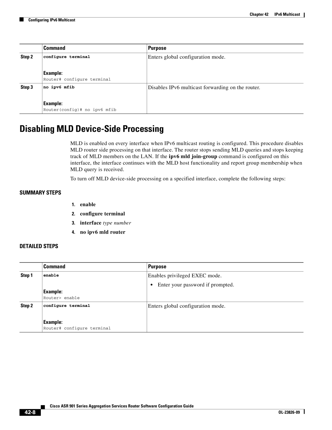
No ipv6 mld router
Disables IPv6 multicast forwarding on the router
Disabling MLD Device-Side Processing
42-8
Configuring MLD Protocol on an Interface
42-9
No ipv6 mld router
Configuring a Rendezvous Point
42-10
Configuring PIM SSM Options
Enable Configure terminal Ipv6 pim
42-11
Disabling PIM SSM Multicast on an Interface
Configuring IPv6 SSM Mapping
Disables PIM on the specified interface
No ipv6 pim
No ipv6 mld vrf vrf-namessm-map query dns
Configure terminal Ipv6 mld vrf vrf-namessm-map enable
Verifying IPv6 Multicast
42-13
Router# show ipv6 mld traffic
42-14
Router# show ipv6 mld interface gigabitethernet 0/1
Router# show ipv6 pim interface
42-15
Router# show ipv6 mld groups summary
Router# show ipv6 pim neighbor count
Router# show ipv6 mroute
42-16
Router# show ipv6 pim neighbor
Router# show ipv6 pim topology
Router# show ipv6 pim group-map FF0EE0111
42-17
Router# show ipv6 pim topology route-count
Router# show ipv6 pim range-list
42-18
Router# show ipv6 pim traffic
Router# show ipv6 pim join-prune statistic
Following example
42-19
Router# show ipv6 mfib summary
42-20
Router# show ipv6 mfib status
Router# show ipv6 mfib interface
Example Enabling IPv6 Multicast Routing
Configuration Examples for IPv6 Multicast
Example Configuring IPv6 SSM Mapping
42-21
Command Name Description
42-22
42-23
Feature Information for IPv6 Multicast
Chapter of the IP Multicast PIM Configuration Guide
42-24
Chapter of the IP Multicast LSM Configuration Guide
42-25
42-26
Configuring Switched Port Analyzer
Span Limitations and Configuration Guidelines
43-1
Understanding Span
Following sections describe Span
43-2
Span Session
Source Interface
43-3
Traffic Types
Configuring Span
Destination Interface
Span Traffic
Removing Sources or Destination from a Span Session
43-5
Clears existing Span configuration for a session
Configuration Examples for Span
Enable Configure terminal No monitor session sessionnumber
Verifying Local Span
43-7
Rspan Vlan
43-8
Feature Information for Switched Port Analyzer
43-9
43-10
See BSC
IN-1
IN-2
IN-3
IN-4
IN-5
See MSC
IN-6
IN-7
IN-8
IN-9
IN-10