Monitoring and protective functions | 8 |
8.1Power unit protection, general
Description
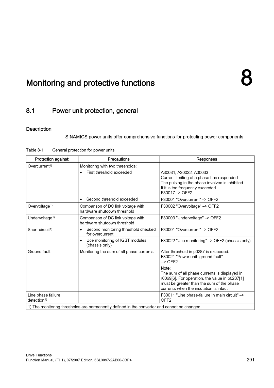
SINAMICS power units offer comprehensive functions for protecting power components.
Table | General protection for power units |
|
| ||
|
|
|
|
| |
Protection against: |
| Precautions |
| Responses | |
Overcurrent1) |
| Monitoring with two thresholds: |
|
| |
|
| • | First threshold exceeded | A30031, A30032, A30033 | |
|
|
|
| Current limiting of a phase has responded. | |
|
|
|
| The pulsing in the phase involved is inhibited. | |
|
|
|
| If it is too frequently exceeded | |
|
|
|
| F30017 | |
|
| • | Second threshold exceeded | F30001 | "Overcurrent" |
Overvoltage1) | Comparison of DC link voltage with | F30002 | "Overvoltage" | ||
|
| hardware shutdown threshold |
|
| |
Undervoltage1) | Comparison of DC link voltage with | F30003 | "Undervoltage" | ||
|
| hardware shutdown threshold |
|
| |
| • Second monitoring threshold checked | F30001 | "Overcurrent" | ||
|
|
| for overcurrent |
|
|
|
| • Uce monitoring of IGBT modules | F30022 | "Uce monitoring" | |
|
|
| (chassis only) |
|
|
Ground fault |
| Monitoring the sum of all phase currents | After threshold in p0287 is exceeded: | ||
|
|
|
| F30021 | "Power unit: ground fault" |
|
|
|
| ||
|
|
|
| Note: |
|
|
|
|
| The sum of all phase currents is displayed in | |
|
|
|
| r0069[6]. For operation, the value in p0287[1] | |
|
|
|
| must be greater than the sum of the phase | |
|
|
|
| currents when the insulation is intact. | |
Line phase failure |
|
| F30011 | "Line | |
detection1) |
|
|
| OFF2 |
|
1) The monitoring thresholds are permanently defined in the converter and cannot be changed.
Drive Functions | 291 |
Function Manual, (FH1), 07/2007 Edition, |