|
|
|
| Communication PROFIBUS DP/PROFINET IO | |
|
|
|
| 10.3 Communications via PROFINET IO | |
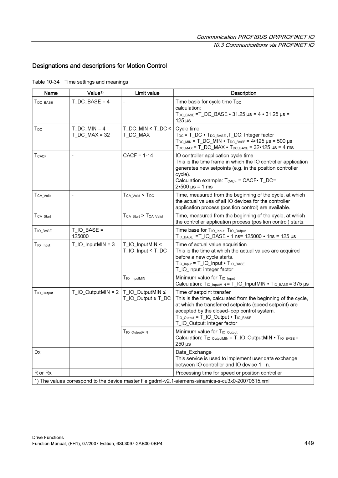
| Designations and descriptions for Motion Control |
|
| ||
| Table |
|
| ||
|
|
|
|
|
|
| Name | Value1) | Limit value | Description | |
| TDC_BASE | T_DC_BASE = 4 | - | Time basis for cycle time TDC | |
|
|
|
| calculation: | |
|
|
|
| TDC_BASE =T_DC_BASE ∙ 31.25 µs = 4 ∙ 31.25 µs = | |
|
|
|
| 125 µs |
|
| TDC | T_DC_MIN = 4 | T_DC_MIN ≤ T_DC ≤ | Cycle time | |
|
| T_DC_MAX = 32 | T_DC_MAX | TDC = T_DC ∙ TDC_BASE ,T_DC: Integer factor | |
|
|
|
| TDC_MIN = T_DC_MIN ∙ TDC_BASE = 4∙125 µs = 500 µs | |
|
|
|
| TDC_MAX = T_DC_MAX ∙ TDC_BASE = 32∙125 µs = 4 ms |
|
| TCACF | - | CACF = | IO controller application cycle time | |
|
|
|
| This is the time frame in which the IO controller application | |
|
|
|
| generates new setpoints (e.g. in the position controller | |
|
|
|
| cycle). | |
|
|
|
| Calculation example: TCACF = CACF∙ T_DC= | |
|
|
|
| 2∙500 µs = 1 ms |
|
| TCA_Valid | - | TCA_Valid < TDC | Time, measured from the beginning of the cycle, at which | |
|
|
|
| the actual values of all IO devices for the controller | |
|
|
|
| application process (position control) are available. |
|
| TCA_Start | - | TCA_Start > TCA_Valid | Time, measured from the beginning of the cycle, at which | |
|
|
|
| the controller application process (position control) starts. |
|
| TIO_BASE | T_IO_BASE = |
| Time base for TIO_Input, TIO_Output | |
|
| 125000 |
| TIO_BASE =T_IO_BASE ∙ 1 ns= 125000 ∙ 1ns = 125 µs |
|
| TIO_Input | T_IO_InputMIN = 3 | T_IO_InputMIN < | Time of actual value acquisition | |
|
|
| T_IO_Input ≤ T_DC | This is the time at which the actual values are acquired | |
|
|
|
| before a new cycle starts. | |
|
|
|
| TIO_Input = T_IO_Input ∙ TIO_BASE | |
|
|
|
| T_IO_Input: integer factor |
|
|
|
| TIO_InputMIN | Minimum value for TIO_Input | |
|
|
|
| Calculation: TIO_InputMIN = T_IO_InputMIN ∙ TIO_BASE = 375 µs |
|
| TIO_Output | T_IO_OutputMIN = 2 | T_IO_OutputMIN ≤ | Time of setpoint transfer | |
|
|
| T_IO_Output ≤ T_DC | This is the time, calculated from the beginning of the cycle, | |
|
|
|
| at which the transferred setpoints (speed setpoint) are | |
|
|
|
| accepted by the | |
|
|
|
| TIO_Output = T_IO_Output ∙ TIO_BASE | |
|
|
|
| T_IO_Output: integer factor |
|
|
|
| TIO_OutputMIN | Minimum value for TIO_Output | |
|
|
|
| Calculation: TIO_OutputMIN = T_IO_OutputMIN ∙ TIO_BASE = | |
|
|
|
| 250 µs |
|
| Dx |
|
| Data_Exchange | |
|
|
|
| This service is used to implement user data exchange | |
|
|
|
| between IO controller and IO device 1 - n. |
|
| R or Rx |
|
| Processing time for speed or position controller |
|
1) The values correspond to the device master file
Drive Functions | 449 |
Function Manual, (FH1), 07/2007 Edition, |