Appendix
A.2 Availability of SW functions
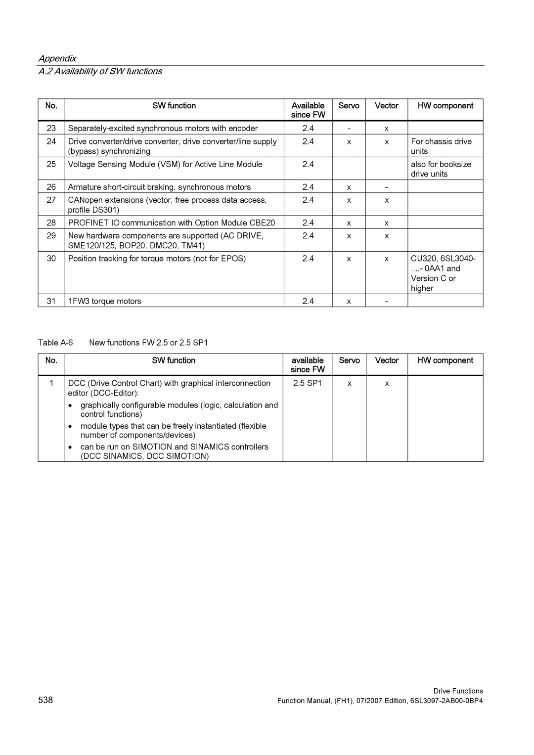
No. |
| SW function | Available | Servo | Vector | HW component |
|
|
| since FW |
|
|
|
23 | 2.4 | - | x |
| ||
24 | Drive converter/drive converter, drive converter/line supply | 2.4 | x | x | For chassis drive | |
| (bypass) synchronizing |
|
|
| units | |
25 | Voltage Sensing Module (VSM) for Active Line Module | 2.4 |
|
| also for booksize | |
|
|
|
|
|
| drive units |
26 | Armature | 2.4 | x | - |
| |
27 | CANopen extensions (vector, free process data access, | 2.4 | x | x |
| |
| profile DS301) |
|
|
|
| |
28 | PROFINET IO communication with Option Module CBE20 | 2.4 | x | x |
| |
29 | New hardware components are supported (AC DRIVE, | 2.4 | x | x |
| |
| SME120/125, BOP20, DMC20, TM41) |
|
|
|
| |
30 | Position tracking for torque motors (not for EPOS) | 2.4 | x | x | CU320, 6SL3040- | |
|
|
|
|
|
| ....- 0AA1 and |
|
|
|
|
|
| Version C or |
|
|
|
|
|
| higher |
31 | 1FW3 torque motors | 2.4 | x | - |
| |
Table | New functions FW 2.5 or 2.5 SP1 |
|
|
|
| |
No. | SW function |
1DCC (Drive Control Chart) with graphical interconnection editor
•graphically configurable modules (logic, calculation and control functions)
•module types that can be freely instantiated (flexible number of components/devices)
•can be run on SIMOTION and SINAMICS controllers
(DCC SINAMICS, DCC SIMOTION)
available since FW
2.5 SP1
Servo | Vector | HW component |
|
|
|
x | x |
|
|
|
|
538 | Drive Functions |
Function Manual, (FH1), 07/2007 Edition, |