Vector control
4.12 Motor data identification and rotating measurement
For control engineering reasons, you are strongly advised to carry out motor identification because the equivalent circuit diagram data, motor cable resistance, IGBT
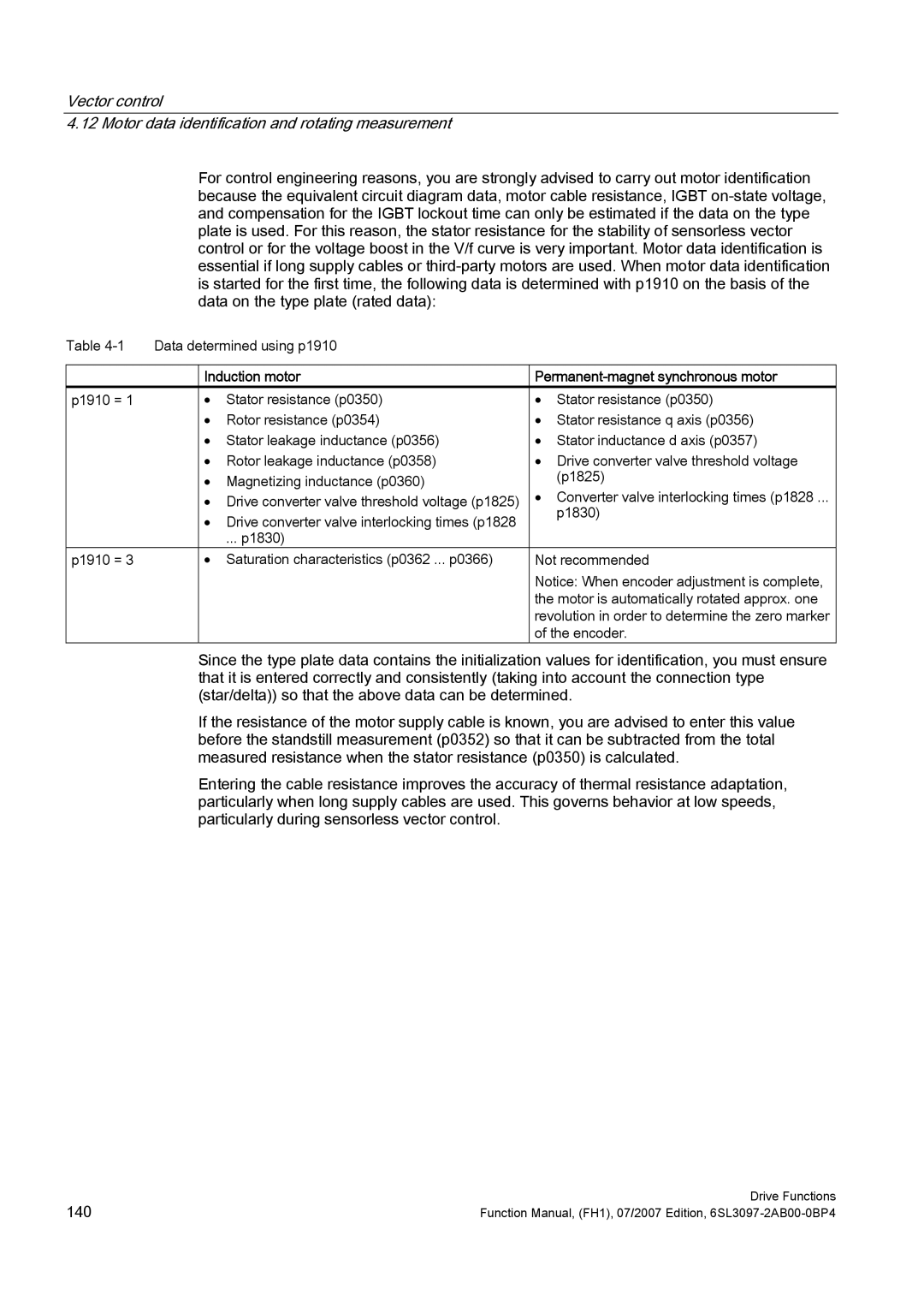
Table | Data determined using p1910 |
| ||
|
|
|
| |
|
| Induction motor | ||
p1910 = 1 |
| • | Stator resistance (p0350) | • Stator resistance (p0350) |
|
| • | Rotor resistance (p0354) | • Stator resistance q axis (p0356) |
|
| • Stator leakage inductance (p0356) | • Stator inductance d axis (p0357) | |
|
| • Rotor leakage inductance (p0358) | • Drive converter valve threshold voltage | |
|
| • | Magnetizing inductance (p0360) | (p1825) |
|
| • Drive converter valve threshold voltage (p1825) | • Converter valve interlocking times (p1828 ... | |
|
| • Drive converter valve interlocking times (p1828 | p1830) | |
|
|
| ||
|
|
| ... p1830) |
|
p1910 = 3 |
| • | Saturation characteristics (p0362 ... p0366) | Not recommended |
|
|
|
| Notice: When encoder adjustment is complete, |
|
|
|
| the motor is automatically rotated approx. one |
|
|
|
| revolution in order to determine the zero marker |
|
|
|
| of the encoder. |
Since the type plate data contains the initialization values for identification, you must ensure that it is entered correctly and consistently (taking into account the connection type (star/delta)) so that the above data can be determined.
If the resistance of the motor supply cable is known, you are advised to enter this value before the standstill measurement (p0352) so that it can be subtracted from the total measured resistance when the stator resistance (p0350) is calculated.
Entering the cable resistance improves the accuracy of thermal resistance adaptation, particularly when long supply cables are used. This governs behavior at low speeds, particularly during sensorless vector control.
140 | Drive Functions |
Function Manual, (FH1), 07/2007 Edition, |