Communication PROFIBUS DP/PROFINET IO 10.2 Communication via PROFIBUS DP
Sequence of data transfer to closed-loop control system
1.Position actual value G1_XIST1 is read into the telegram image at time TI before the start of each cycle and transferred to the master in the next cycle.
2.
3.In the next cycle, the master transmits the calculated setpoints to the telegram image of the slaves. The speed setpoint command NSOLL_B is issued to the
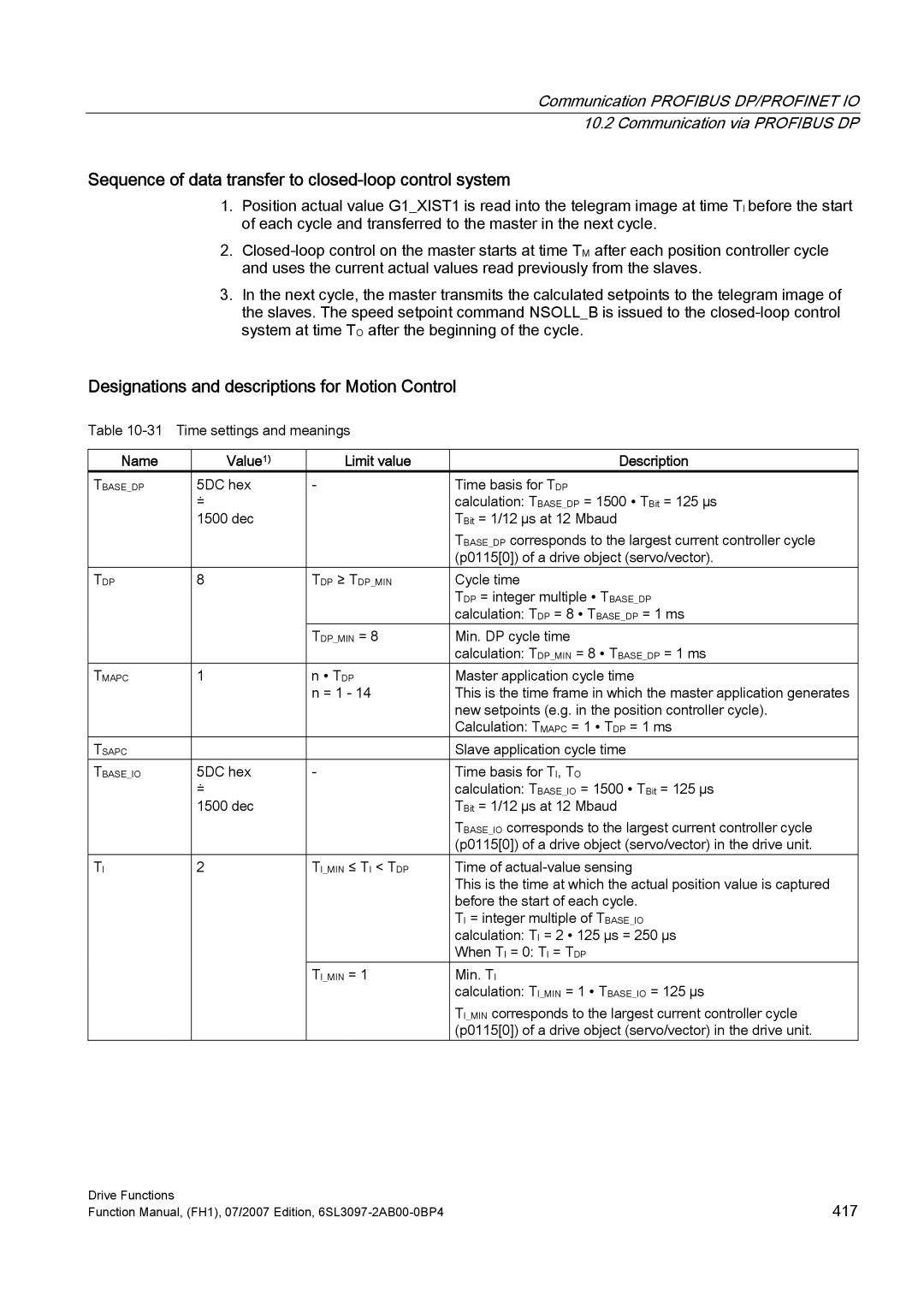
Designations and descriptions for Motion Control
Table
Name | Value1) | Limit value | Description |
TBASE_DP | 5DC hex | - | Time basis for TDP |
| ≐ |
| calculation: TBASE_DP = 1500 ∙ TBit = 125 µs |
| 1500 dec |
| TBit = 1/12 µs at 12 Mbaud |
|
|
| TBASE_DP corresponds to the largest current controller cycle |
|
|
| (p0115[0]) of a drive object (servo/vector). |
TDP | 8 | TDP ≥ TDP_MIN | Cycle time |
|
|
| TDP = integer multiple ∙ TBASE_DP |
|
|
| calculation: TDP = 8 ∙ TBASE_DP = 1 ms |
|
| TDP_MIN = 8 | Min. DP cycle time |
|
|
| calculation: TDP_MIN = 8 ∙ TBASE_DP = 1 ms |
TMAPC | 1 | n ∙ TDP | Master application cycle time |
|
| n = 1 - 14 | This is the time frame in which the master application generates |
|
|
| new setpoints (e.g. in the position controller cycle). |
|
|
| Calculation: TMAPC = 1 ∙ TDP = 1 ms |
TSAPC |
|
| Slave application cycle time |
TBASE_IO | 5DC hex | - | Time basis for TI, TO |
| ≐ |
| calculation: TBASE_IO = 1500 ∙ TBit = 125 µs |
| 1500 dec |
| TBit = 1/12 µs at 12 Mbaud |
|
|
| TBASE_IO corresponds to the largest current controller cycle |
|
|
| (p0115[0]) of a drive object (servo/vector) in the drive unit. |
TI | 2 | TI_MIN ≤ TI < TDP | Time of |
|
|
| This is the time at which the actual position value is captured |
|
|
| before the start of each cycle. |
|
|
| TI = integer multiple of TBASE_IO |
|
|
| calculation: TI = 2 ∙ 125 µs = 250 µs |
|
|
| When TI = 0: TI = TDP |
|
| TI_MIN = 1 | Min. TI |
|
|
| calculation: TI_MIN = 1 ∙ TBASE_IO = 125 µs |
|
|
| TI_MIN corresponds to the largest current controller cycle |
|
|
| (p0115[0]) of a drive object (servo/vector) in the drive unit. |
Drive Functions | 417 |
Function Manual, (FH1), 07/2007 Edition, |