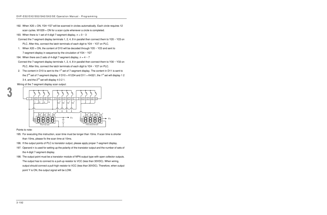
192.When X20 = ON, Y24~Y27 will be scanned in circles automatically. Each circle requires 12 scan cycles. M1029 = ON for a scan cycle whenever a circle is completed.
193.When there is 1 set of
Connect the
1.When X20 = ON, the content of D10 will be decoded through Y20 ~ Y23 and sent to
194. When there are 2 sets of
Connect the
2.The content in D10 is sent to the 1st set of
3 4, and the 2nd set will display 4 3 2 1. Wiring of the
C | Y20 | Y21 | Y22 | Y23 | C | Y24 |
| Y25 |
| Y26 |
| Y27 | C | Y30 | Y31 | Y32 | Y33 |
|
| 1 | 2 | 4 | 8 |
| 10 | 0 | 10 | 1 | 10 | 2 | 10 | 3 |
|
|
|
|
|
|
|
|
|
|
|
|
|
|
|
|
|
|
|
| ||||
|
| 103 | 102 | 101 | 100 |
|
|
|
|
|
|
|
|
| 103 | 102 | 101 | 100 |
| 1 |
|
|
|
|
|
|
|
|
|
| V+ |
| 1 |
|
|
| V+ |
| 2 |
|
|
|
|
|
|
|
|
|
|
| 2 |
|
|
| ||
| 4 |
|
|
|
|
|
|
|
|
|
|
|
| 4 |
|
|
| |
| 8 |
|
|
|
|
|
|
|
|
|
|
|
| 8 |
|
|
|
|
|
| The first set |
|
|
|
|
|
|
|
|
|
| The second set |
| ||||
Points to note:
195.For executing this instruction, scan time must be longer than 10ms. If scan time is shorter than 10ms, please fix the scan time at 10ms.
196.If the output points of PLC is transistor output, please apply proper
197.Operand n is used for setting up the polarity of the transistor output and the number of sets of the
198.The output point must be a transistor module of NPN output type with open collector outputs. The output has to connect to a
