2
5.Click Save to make your change permanent.
The entry for the logical VLAN interface disappears from the Logical Interfaces table.
To define the maximum number of VLANs
1.Click Interfaces under Configuration > Interface Configuration in the tree view.
2.Enter a number in the Maximum Number of VLANs Allowed text box. The maximum value is 1015.
3.Click Apply.
4.Click Save to make your change permanent.
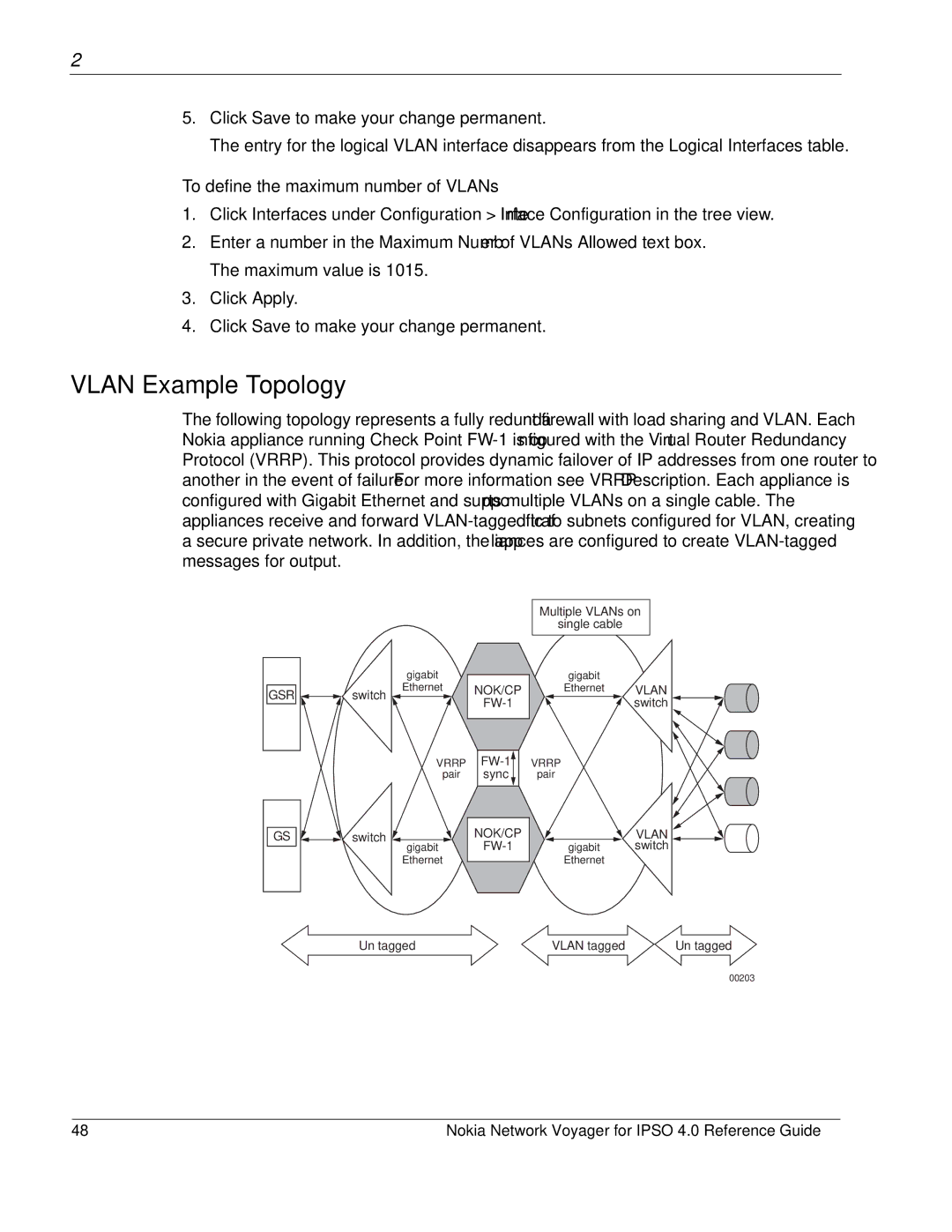
VLAN Example Topology
The following topology represents a fully redundant firewall with load sharing and VLAN. Each Nokia appliance running Check Point
Multiple VLANs on
single cable
|
| gigabit |
GSR | switch | Ethernet |
|
VRRP
pair
NOK/CP
sync |
gigabit
Ethernet VLAN
switch ![]()
![]()
VRRP
pair
GS | switch |
| gigabit |
| Ethernet |
NOK/CP
VLAN
gigabit switch Ethernet
Un tagged | VLAN tagged | Un tagged |
00203
48 | Nokia Network Voyager for IPSO 4.0 Reference Guide |