19.Click the logical interface name in the Interface column of the Logical interfaces table to go the Interface page.
20.Enter the IP address for the local end of the PVC in the Local address text box.
21.Enter the IP address of the remote end of the PVC in the Remote address text box. Click Apply.
22.(Optional) Change the interfaces logical name to a more meaningful name by typing the preferred name in the Logical name text box.
23.Click Apply.
24.Click Save to make your changes permanent.
Serial Interface Example
This section describes how you might configure the interfaces of your IP security platform in an example network, using Network Voyager.
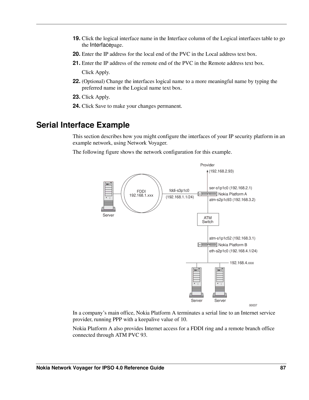
The following figure shows the network configuration for this example.
FDDI | |
192.168.1.xxx | (192.168.1.1/24) |
| |
Server |
|
Provider ![]() (192.168.2.93)
(192.168.2.93)
![]()
![]()
![]()
![]()
![]()
![]()
![]()
![]()
![]() Nokia Platform A
Nokia Platform A
ATM
Switch
![]()
![]()
![]()
![]()
![]()
![]()
![]()
![]()
![]() Nokia Platform B
Nokia Platform B
192.168.4.xxx
Server |
Server |
00037
In a company’s main office, Nokia Platform A terminates a serial line to an Internet service provider, running PPP with a keepalive value of 10.
Nokia Platform A also provides Internet access for a FDDI ring and a remote branch office connected through ATM PVC 93.
Nokia Network Voyager for IPSO 4.0 Reference Guide | 87 |