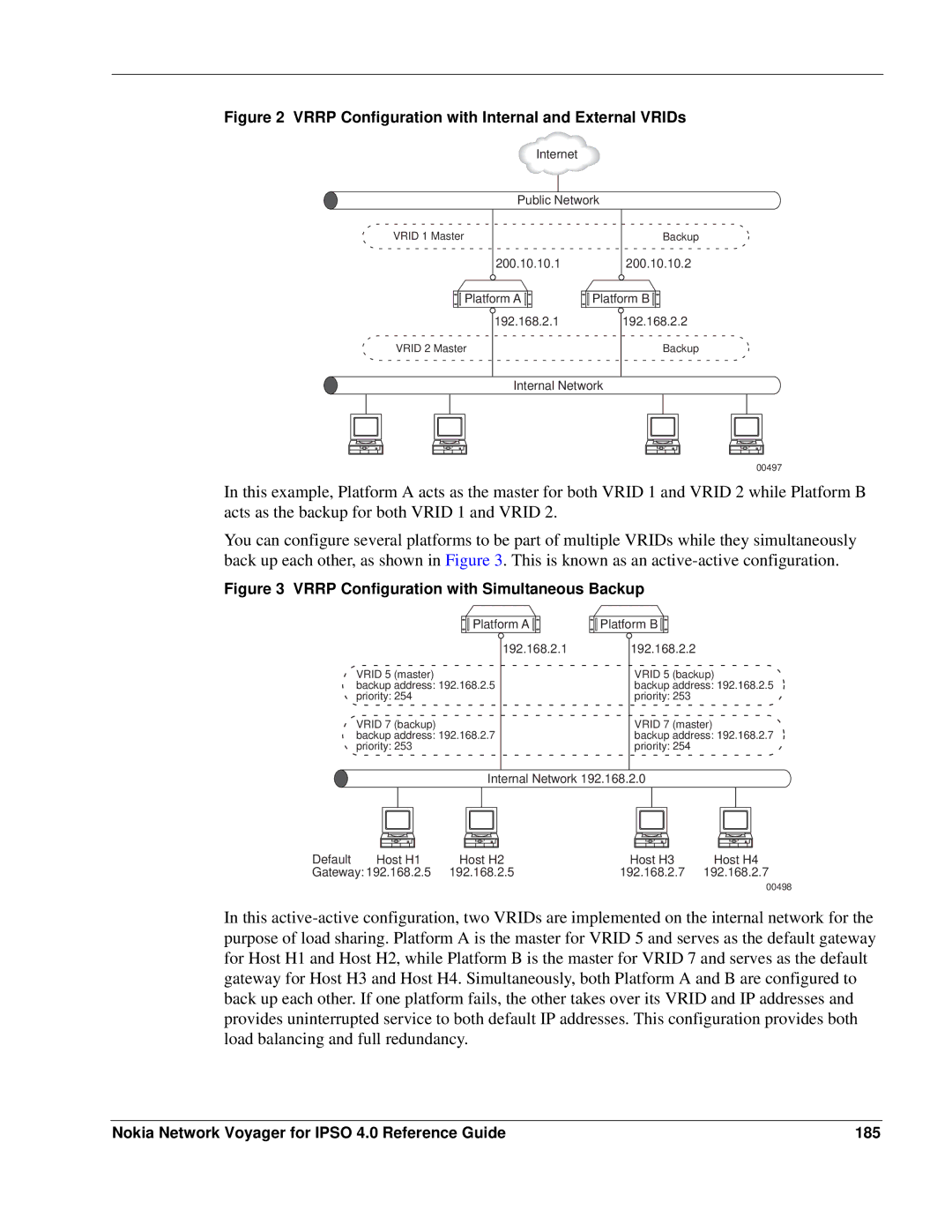
Figure 2 VRRP Configuration with Internal and External VRIDs
Internet
Public Network
VRID 1 Master | Backup |
200.10.10.1200.10.10.2
Platform A | Platform B |
192.168.2.1 | 192.168.2.2 |
VRID 2 Master | Backup |
Internal Network
00497
In this example, Platform A acts as the master for both VRID 1 and VRID 2 while Platform B acts as the backup for both VRID 1 and VRID 2.
You can configure several platforms to be part of multiple VRIDs while they simultaneously back up each other, as shown in Figure 3. This is known as an
Figure 3 VRRP Configuration with Simultaneous Backup
Platform A | Platform B |
VRID 5 (master)
backup address: 192.168.2.5
priority: 254
VRID 7 (backup)
backup address: 192.168.2.7
priority: 253
192.168.2.1
192.168.2.2
VRID 5 (backup)
backup address: 192.168.2.5
priority: 253
VRID 7 (master)
backup address: 192.168.2.7
priority: 254
Internal Network 192.168.2.0
Default | Host H1 | Host H2 | Host H3 | Host H4 |
Gateway: 192.168.2.5 | 192.168.2.5 | 192.168.2.7 | 192.168.2.7 | |
00498
In this
Nokia Network Voyager for IPSO 4.0 Reference Guide | 185 |