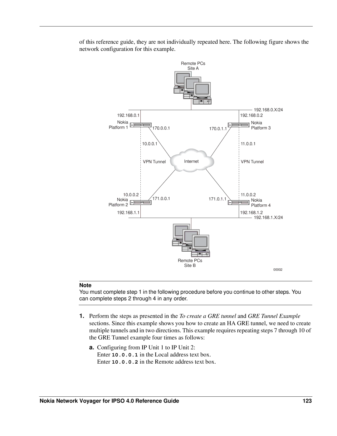
of this reference guide, they are not individually repeated here. The following figure shows the network configuration for this example.
Remote PCs
Site A
192.168.0.1 |
|
|
|
|
|
|
| |||||
Nokia |
|
|
|
|
|
|
|
|
|
|
|
|
Platform 1 |
|
|
|
|
|
|
|
|
|
| 170.0.0.1 | 170.0.1.1 |
|
|
|
|
|
| 10.0.0.1 |
| |||||
|
|
|
|
|
| VPN Tunnel | Internet | |||||
192.168.0.X/24
192.168.0.2
Nokia Platform 3
11.0.0.1
VPN Tunnel
10.0.0.2 Nokia
Platform 2 ![]() 192.168.1.1
192.168.1.1
171.0.0.1171.0.1.1
11.0.0.2
Nokia
Platform 4
192.168.1.2
192.168.1.X/24
Remote PCs
Site B
00002
Note
You must complete step 1 in the following procedure before you continue to other steps. You can complete steps 2 through 4 in any order.
1.Perform the steps as presented in the To create a GRE tunnel and GRE Tunnel Example sections. Since this example shows you how to create an HA GRE tunnel, we need to create multiple tunnels and in two directions. This example requires repeating steps 7 through 10 of the GRE Tunnel example four times as follows:
a.Configuring from IP Unit 1 to IP Unit 2: Enter 10.0.0.1 in the Local address text box. Enter 10.0.0.2 in the Remote address text box.
Nokia Network Voyager for IPSO 4.0 Reference Guide | 123 |